Download

1 / 15
150 likes | 331 Views
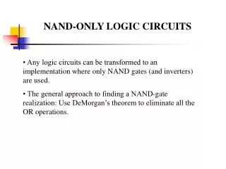
Evaluation of Dynamic NAND-NAND Programmable Logic Array. Prasanth Jampani (jampani@neo.tamu.edu). Introduction. Programmable logic array (PLA) is a circuit realization for two-level sum of products representation of a multi-output Boolean function.

E N D
Evaluation of Dynamic NAND-NAND Programmable Logic Array Prasanth Jampani (jampani@neo.tamu.edu)
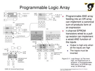
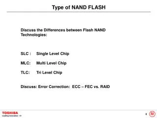
Introduction • Programmable logic array (PLA) is a circuit realization for two-level sum of products representation of a multi-output Boolean function. • It is a regular structure for implementing multi-output Boolean functions. • The programming of the PLA can be modified at the later stages of the design process without having to re-do the whole layout. • Take N inputs and produce M outputs • Each input represents a logical variable • Each output represents a logical function output • Different types: • AND - OR • NAND – NAND • NOR – NOR • Implemented in static or dynamic styles. • Style is chosen depending on the timing and power strategies.
Scope of the work • Implementation of any logic functions in a dynamic NAND-NAND PLA. • Perl code to generate the spice deck for any ‘m’ input and ‘n’ output PLA • Spice simulations for power and delay characterization by varying • number of inputs • number of outputs • number of cubes • Layout • Space 3D to extract the interconnect parasitics • Post Layout Simulation • Some ideas to improve the delay and power consumption.
Control Flow Input File Draw Layout gds Perl Code Space 3D Extract Spice Capacitance File Spice Deck No Output OK simulation Yes Calculate Area Calculate Delay, Power
Operation • Pre-charging phase • Horizontal word lines and the outputs get pre-charged with a strong pull-up transistors. • Evaluation phase • When the CLK switches high, the PLA enters the evaluation phase. • If all the bit lines of a particular word line are high, it gets pulled low. • A special line called the dummy line is introduced which is maximally loaded among all the word lines to generate the delayed clock for the OR plane. • Dummyline is designed to be the last word line to get switched. • An inverter is connected to the output of the dummy line which generates the delayed clock with the skew of maximum possible delay possible in the AND plane. • This delayed clock is used to turn on the ground gating transistor in the OR plane. • The output lines to which, only the word lines that have remained high are connected will switch low.
Delay Calculation • To measure the delay of the NAND-NAND PLA, a new completion line is introduced at the output. • It represents the maximal loading at the output plane taking into consideration the number of cubes in each of the outputs. • Total delay = delay of the Dummyline + delay of the Completion line. • Delay is independent of the logic function.
Simulation Results - 1 Simulation output for a 2 input, 3 cubes and 2 output PLA. Out1 = A XOR B, Out2 = AB + A`B
Delay and power characterization Delay in ns Value Value Power in mW Number of Inputs Number of Inputs Number of cubes = 3 Number of outputs = 2 Number of cubes = 4 Number of outputs = 2
Delay and power characterization (cont..) Delay in ns Value Power in mW Number of Inputs Number of cubes = 8 Number of outputs = 2
Layout Area = 12.24 X 9.99 micron
Post Layout • Post layout simulations are performed on a 2 input and 2 output PLA • Interconnect capacitances are extracted from the layout using Space 3D • Interconnect resistance values are calculated manually • Parasitic information is fed back to the SPICE netlist Table1: Pre and Post layout simulation results on a 2 input, 2 output PLA
Delay and Power optimization • Power: • Keeper Transistors instead of static pull-ups • Delay: • Transmission gate to cutoff the AND plane during the pre-charge phase. • A buffer is inserted to overcome any functional errors.
Results • Transmission gate • Keeper Transistors instead of static pull-ups (Post layout simulation)