Download
1 / 9
130 likes | 577 Views
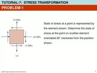
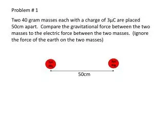
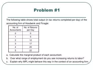
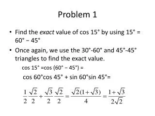
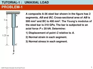
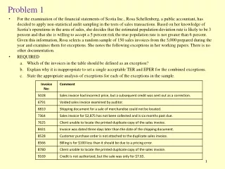
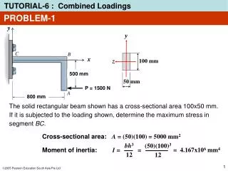
y. z. 100 mm. 50 mm. PROBLEM-1. y. The solid rectangular beam shown has a cross-sectional area 100x50 mm . If it is subjected to the loading shown, determine the maximum stress in segment BC . x. 500 mm. P = 1500 N. 800 mm. Cross-sectional area: A = (50)(100) = 5000 mm 2.

E N D
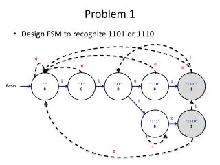
y z 100 mm 50 mm PROBLEM-1 y The solid rectangular beam shown has a cross-sectional area 100x50 mm. If it is subjected to the loading shown, determine the maximum stress in segment BC. x 500 mm P = 1500 N 800 mm Cross-sectional area: A = (50)(100) = 5000 mm2 bh3 12 (50)(100)3 12 Moment of inertia: = 4.167x106 mm4 I= =
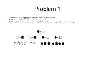
PROBLEM-1 y y y Stress components in segment BC: + P = x x x 500 mm M Bending (negative) M = – P(500) N.mm = – 750 kN.mm Axial Load (negative) P = 1500 N 800 mm 1. Compressive stress due to axial load: s = –0.3MPa • s = – P/A = –1500/5000 = –0.3 N/mm2 s = 1.8 MPa 2. Bending stress: Mc I (–750x103)(50) 4.167x10⁶ s = = = 1.8 N/mm2 s = –1.8 MPa
PROBLEM-1 y y y Maximum bending stress at the upper part of the beam: s = – 0.3 + 1.8 = 1.5 Mpa (tensile) + P = x x x 500 mm M Bending (negative) M = – P(500) N.mm = – 750 kN.mm Axial Load (negative) P = 1500 N 800 mm = + s = –0.3MPa s = 1.5 MPa s = 1.8 MPa Maximum bending stress at the lower part of the beam: • s = –0.3 – 1.8 = –2.1 MPa (compressive) s = –2.1 MPa s = –1.8 MPa
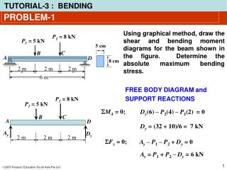
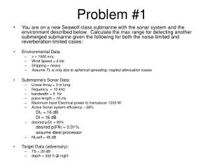
T y x z PROBLEM-2 Stress in Shaft due to Bending Load and Torsion A shaft has a diameter of 4 cm. The cutting section shows in the figure is subjected to a bending moment of2 kNm and a torque of 2.5 kNm. • Determine: • The critical point of the section • The stress state of the critical point.
T A y x z PROBLEM-2 Analysis to identify the critical point • Due to the torque T Maximum shear stresses occur at the peripheral of the section or on the outer surface of the shaft. • Due to the bending moment M Maximum tensile stress occurs at the bottom point (A) of the section. Conclusion: the bottom point (A) is the critical point
198.94MPa 318.31MPa T A y x z PROBLEM-2 Stress components at point A • Due to the torque T 198.94MPa • Due to the bending moment M 318.31MPa Stress state at critical point A txy = 198.94MPa sx = 318.31MPa
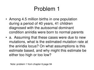
PROBLEM-3 Stress in Shafts Due to Axial Load, Bending and Torsion A shaft has a diameter of 4 cm. The cutting section shows in the figure is subjected to a compressive force of 2500 N, a bending moment of800 Nm and a torque of 1500 Nm. Determine the stress state of point A.
PROBLEM-3 Analysis of the stress components at point A • Due to comprsv load: • Due to torsional load: (compressive stress) • Due to bending load:
txy sx PROBLEM-3 Stress state at point A Shear stress: txy= tA= 119.37 MPa Normal stress: sx= sA’ + sA” = (– 1.99 – 127.32) MPa = – 129.31 MPa