Download
1 / 32
320 likes | 590 Views
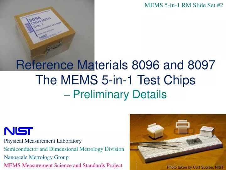
MEMS 5-in-1 RM Slide Set #2. Reference Materials 8096 and 8097 The MEMS 5-in-1 Test Chips – Preliminary Details. Physical Measurement Laboratory Semiconductor and Dimensional Metrology Division Nanoscale Metrology Group MEMS Measurement Science and Standards Project.

E N D
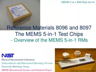
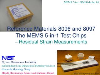
MEMS 5-in-1 RM Slide Set #2 Reference Materials 8096 and 8097 The MEMS 5-in-1 Test Chips – Preliminary Details • Physical Measurement Laboratory • Semiconductor and Dimensional Metrology Division • Nanoscale Metrology Group • MEMS Measurement Science and Standards Project Photo taken by Curt Suplee, NIST
Outline for the Preliminary Details
1a. Processing RM 8096 and 8097 • RM 8096 • Fabricated in a multi-user 1.5 µm CMOS process • Followed by a bulk-micromachining etch at NIST • STEP 1: CF4+O2 etch • STEP 2: XeF2 etch • RM 8097 • Fabricated using a polysilicon multi-user surface-micromachining MEMS process with a backside etch • No additional processing is needed.
1b. Post-Processing RM 8096(CF4+O2 Etch) • STEP 1: Remove the nitride cap (CF4+O2 for ~4 min.) since Young’s modulus standard applies to one layer • Removal of nitride cap verified with stylus step height measurements (before + after the etch) ~2.7 µm SiO2 after CF4+O2 etch Approx. same thickness for oxide over m2 and nitride cap. Nitride cap removed if ~0.5 mm stylus measurement.
released after etch unreleased after etch 1b. Post-Processing RM 8096 (XeF2 Etch) • STEP 2: Release the beams (i.e., to etch the exposed Si around and beneath the designed beams) Isotropic XeF2 etch (using ~25 cycles) 1 cycle: Start with pressure at 1.0 Torr XeF2 released until 3.0 Torr Wait 10 seconds then suck out the XeF2 • Release verified with microscope or interferometer • Biggest issue: debris in attachment corners of beams ~2.7 µm SiO2 after XeF2 etch
1c. Packaging the RMs chip lid PZT • Contents: • RM unit • RM chip atop PZT • Within hybrid package • Lid secured with plastic clip • Sits atop a piece of cleanroom paper • Sealed within a ULO bag with argon gas • Placed within a foam padded wooden box • With a memory stick of pertinent files • Read Me First • ROI • SP260-177 • Data sheets • Shrink wrapped non-conductive epoxy memory stick NIST RM 8096 NIST Customer storage:.. ………… To remove plastic clip:……..
1d. Storage and Handling • Upon receipt of the RM: • Remove the package assembly from the wooden box • Remove the plastic clip • Store in a dust-free inert atmosphere (such as, in N2 or Ar gas) or under an oil-free vacuum at a temperature of 20.5 C ± 1.1 C for optimal parametric stability. • Handling: • Handle using the metal package, without contacting the test chip • The lid should be carefully placed atop the package when the RM is not in use. • Avoid exposing the RM to large temperature variations, temperature cycling, large humidity variations, or mechanical shock. • Particulate contamination may be removed with a low velocity dry N2 flow. Too high or turbulent flow can break the cantilevers so only remove it if it is near the test structure being measured.
Outline for the Preliminary Details
2a. Instruments Used • Optical interferometric microscope (or comparable instrument) • In-plane length • Residual strain • Strain gradient • Step height • Thickness • RM 8096: When applicable platforms are reflective • RM 8097: For measurement of B and/or C (and perhaps A) • Optical vibrometer (or comparable instrument) • Young’s modulus • Stylus profilometer (or comparable instrument) • Thickness • RM 8096: When applicable platforms are not reflective • RM 8097: For measurement of A (for a lower uncertainty value), if used C
2b. A Typical Interferometer (Operated in Static Mode) Obtains sample height data at each pixel location within the field of view. (For in-plane length, residual strain, strain gradient, and step height measurements)
2b. Static Interferometric Data Note that there are some data dropouts as you get farther along the cantilever 20 mm deflection at 220 mm along a 400 mm long CMOS cantilever (at 25x)
2b. A Typical Interferometer (Operated in Dynamic Mode) Obtains successive 3D images as the sample cycles through its range of motion. Plot height vs. frequency to obtain resonance frequency. (For Young’s modulus measurements)
2c. A Typical Vibrometer Obtains voltage proportional to instantaneous velocity. (For Young’s modulus measurements)
2c. Dual Beam Laser Doppler Vibrometer Data Lcan=100 mm, fres=168 kHz Lcan=400 mm, fres=14.3 kHz Plot magnitude vs. frequency to determine resonance frequency. Note 1: This vibrometer “flattens” the z-data and then the oscillation is exaggerated such that it looks like it is oscillating both above and below the xy-plane of the test chip, when in fact it is oscillating entirely above this plane. Note 2: The use of a reference beam gives a wonderfully stable support!
2d. Check Standards / Traceability • Step height standards • To calibrate the interferometer and stylus profilometer (or comparable instruments) in the z-direction • Every data session • Calibrated at NIST (therefore, NIST traceable measurements) • Recalibrate at NIST once every 3 years • Stage micrometer • To calibrate the interferometer (or comparable instrument) in the x- and y-directions • On a yearly basis • Or, after the instrument has been serviced • Has a calibration certificate traceable to NIST measurements • Recalibrate at NIST once every 5 years • Or, purchase a new one • Frequency counter • To calibrate the frequency of the vibrometer (or comparable instrument) • Every data session • Calibrated by the vendor to provide NIST-traceable measurements • Have vendor recalibrate it (with NIST-traceable measurements) once every 5 years
Outline for the Preliminary Details
3a. Expanded Uncertainties and Limits • Stability expanded uncertainty, Ustability • Expanded uncertainty for the ROI, UROI • Homogeneity expanded uncertainty, Uhomog • Heterogeneity limits, Ulimit
3a. Stability Expanded Uncertainty, Ustability • From SP 260-177 [Eq. (30)]: • If assume UM=UR=Uave, then • For a uniform distribution, • Stability expanded uncertainty • (multiply by two, since the initial value is considered the “lowest” value and not the midpoint) • Use for material parameters (YM, RS, SG, RStress, and StressG) • For dimensional parameters (SH, IPL, and T), assume Ustability= 0.0 µm • Can assume that Ustability.For.P1=Ustability.For.P2 UR=exp. unc. reference value UM=exp. unc. of new measured value UD=exp. unc. of difference where D=|MR|
3a. Expanded Uncertainty for the ROI, UROI • The data sheet expanded uncertainty, UDS, and the stability expanded uncertainty, Ustability, are added in quadrature:
3a. Homogeneity Expanded Uncertainty, Uhomog • Uhomog = 2 * stdev(of at least 6 parametric measurements) • Include in ROI for information purposes only • Since each RM was individually measured at NIST • Since adding this component would make the uncertainty unnecessarily high • Can assume that Uhomog.For.P1=Uhomog.For.P2
3a. Heterogeneity Limits • Used to accept or reject RM units received from fabricator • Suggested Ulimit = xUave • Where x is given in the table below • Include in ROI for information purposes only • Can assume that Uave.For.P1=Uave.For.P2
3b. Length of Certification • Connect 2nd and 4th points • Assume 3rd point an estimate for max separation • D=|C-M| • UD=SQRT(UC2+UM2) • Plot C+UD and find intersection • Recommended length of certification is 2 years (to ensure D<UD)
3b. Length of Certification (for Material Parameters) • Domino effect with material parameters • For stability tests, monitor the residual strain
3b. Length of Certification (for Dimensional Parameters) • Dimensional parameters not expected to change with time
Outline for the Preliminary Details
4a. MEMS Calculator Websiteaccessible via http://srdata.nist.gov/gateway/ with the keyword “MEMS Calculator” Includes: 1) Symbol (to help navigate the website) 2) User’s Guide (for downloading) • Data Sheets (for calculations/verification) a) Sample data traces (analyzed) 4) The MEMS 5-in-1 RMs (contact information for ordering) 5) Design and tiff files (for downloading) 6) SEMI standards (and links for ordering) 7) ASTM standards (and links for ordering) 8) MEMS terminology standards (and links for ordering) 9) Other references (for downloading) next slide
4a. Data Sheets(for calculations and verification) • Young’s modulus • Data Sheet YM.3 • Residual strain • Data Sheet RS.3 • Strain gradient • Data Sheet SG.3 • Step height • Data Sheet SH.1.a • Thickness • Data Sheet T.1 (for RM 8096) • Data Sheet T.3.a(for RM 8097) • In-plane length • Data Sheet L.0
4a. Data Sheets(for calculations and data verification) • Each data sheets includes: • Identifying information • Input boxes to fill in • Estimates (if needed) • Sample data • Calculate and verify button • Outputs • How to report the results • Data verification
4b. Correction Terms and Specific Standard Deviations • The correction terms and specific standard deviations used at NIST in the data sheets can be found in the SP 260-177 • In Table 3 on p. 26 (for RM 8096) • In Table 4 on p. 27-28 (for RM 8097)
Outline for the Preliminary Details
5a. Each Measurement Slide Set Includes (if applicable):