Download
1 / 19
190 likes | 307 Views
GAS DISTRIBUTION SYSTEM & FLOW STUDIES OF MM-NSW. T. Alexopoulos, S. Maltezos, S. Karentzos National Technical University of Athens. Outline -- Updates. Updated design and configuration of the gas distribution system Results from the simulation ( “ Pipe-Flow ” ) Gas Flow Studies.

E N D
GAS DISTRIBUTION SYSTEM & FLOW STUDIES OF MM-NSW T. Alexopoulos, S. Maltezos, S. Karentzos National Technical University of Athens
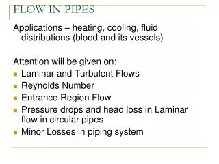
Outline -- Updates • Updated design and configuration of the gas distribution system • Results from the simulation (“Pipe-Flow”) • Gas Flow Studies
What is available for the gas system? • Total gas volume is 6 m3 (Ar:CO2 93:7 at atm. pressure) • Flow rate (renewals): ≤ 10 volume changes a day (flow rate ~2500 l/h) • Existing CSC gas racks (Ar:CO2 80:20 at atm. pressure) with 16 channels/rack can be reused (1 rack/wheel) • Existing MDT gas racks (Ar:CO2 93:7 at 3 bar) with 17 channels/rack can be easily adapted to atm. pressure (1 rack/wheel) SM2 LM2 For each wheel: 16 sectors x 2 typeMM/sector x 2 MP/typeMM = 64 Multiplet (MM types: LM1&2 or SM1&2) SM1 LM1 we use 16 channels/wheel A gas channel serves 4 MP or 2 wedges Total cost ~13 KCHF/year for r =10 volume_changes/day
Gas manifold gas-outlet Gas manifold d=12 mm multiplet multiplet LM2 LM2 wedge multiplet multiplet LM1 LM1 A gas channel impedance impedance gas-inlet Gas manifold Gas manifold d=10 mm
Updated impedances Individual flow rate in each type of MM Feasible to manipulate the flow rates in a controllable way Gas input Flow rate Qt Gas output MM detectors (LM1+LM2, SM1+SM2) Impedances Zi Qi Zi+1 Qi+1 In the case that we would like to accomplish individual flow rates among the MMs, according to their renewal rates, we have to solve analytically the piping network (the pressure – flow rate relation is, in principle, non-linear). Use “Pipe-Flow” simulation. Z8 Qn One impedance will serve two multiplets (LM1+LM2 or SM1+SM2 inner or outer) . We need 64 impedancesin total of two different characteristic curves.
Gas distribution for LM1+LM2 Inner MP –“PipeFlow” The inner LM1+LM2 multiplets is supplied by 4 channels (Ch. 1, 2, 3, 4)
Gas distribution for SM1+SM2 Inner MP The inner SM1+SM2 multiplets is supplied by 4 channels (Ch. 5, 6, 7, 8)
Gas Flow in LM1, radially Geometry: dhole= 0.5mm, dbz= 5mm, din = dout= 2mm. Buffer zone: 1. nhole (1) = 13 2. nhole (2) = 17 0.5mm 2 2mm 2mm LM1 1 5mm
Comparison…………………………………………………………………………………………………………………………………………………………………………………………a. plus 2 “outboard”holes b. without the 2 “outboard” holes Air Ar:CO2
LM1 side”wall” buffer zone Geometry : nholes = 12. Mixed diameters (Model E-like). 1x1.00 4x0.75 0.5 OUTLET INLET 0.5 4x0.75 1x1.00
Air Ar:CO2 Plus center hole
LM1 and LM2 outlet outlet d = 5mm 4 d = 2mm d = 2mm 0.5mm 2mm 5mm LM2 d = 5mm 3 d = 2mm d = 2mm Geometry: dhole = 0.5mm dbz= 5mm Buffer zone: 1. nhole = 13 2. nhole = 17 3. nhole = 17,dhole = 0.5mm, 7 central dhole = 1mm 4. nhole =15 2 d = 5mm LM1 1 d = 5mm Inlet Inlet d = 2mm d = 2mm
LM1 and LM2 Air Ar:CO2
Summary & on going work • The configuration in which the gas goes through multi-planes instead of single planes-layer has been studied and simulated by using the “Pipe Flow”. We assumed 16 gas channels per Wheel. • The functional curves of the impedances have been updated. In this configuration we need 32 impedances per Wheel. • From the simulation “Pipe-Flow” conclude that the gas flow through the multi-planes seem adequate uniform. • Individual plane-layer gas flow simulation has been performed to study the uniformity of the gas flow. • More work on model of gas diffusion through mesh is in progress…