Download
1 / 17
170 likes | 304 Views
CAEN power supplies The neverending story. Jennifer Pursley Johns Hopkins University Silicon Workshop II, May 10-12, 2006 University of California, Santa Barbara. System overview:. Diagram courtesy of J. R. Mumford. Infrastructure: the SY527 Universal Multichannel Power Supply system.

E N D
CAEN power suppliesThe neverending story Jennifer Pursley Johns Hopkins University Silicon Workshop II, May 10-12, 2006 University of California, Santa Barbara
System overview: Diagram courtesy of J. R. Mumford J. Pursley - Silicon Workshop II
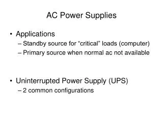
Infrastructure: the SY527Universal Multichannel Power Supply system • CAEN mainframe, has 10 board slots • NOT custom-made, also used for plug power supplies • Communicates via serial connection (RS232 port or CAENET coaxial cable) • Control power supplies (settings and on/off) from front panel • NOT radiation hard, but located in the collision hall! • These are what you hockerize (reboot the crate CPU) J. Pursley - Silicon Workshop II
Collision Hall Map: 16 crates • Mounted on CH walls, with fib racks • 4 crates in each corner, numbered clockwise (sort of…) • Roughly, 2 PS crates = 1 fib • Even number fib is SVX, odd is ISL/L00 Diagram courtesy of M. Stanitzki J. Pursley - Silicon Workshop II
Crate Naming Conventions West Side J. Pursley - Silicon Workshop II
Crate Naming Conventions East Side J. Pursley - Silicon Workshop II
The Workhorse: SVX Modules (A509) • Occupies 1 slot in SY527 • 1 board powers 1 wedge • 5 Bias channels • 5 Low voltage (AVDD & DVDD) • 2 portcard (2V & 5V DOIMs) • Total: 18 channels • 73 supplies in CH (72 for SVX wedges, 1 for a L00 wedge) • VMax = 250V, IMax = 5 mA • Cable pinouts designed for SVX J. Pursley - Silicon Workshop II
Next up: ISL Modules (A510) • Occupies 2 slots in SY527 • 1 board powers 1 wedge • 10 Bias channels • 5 Low voltage (AVDD & DVDD) • 2 portcard (2V & 5V DOIMs) • Total: 23 channels • 30 supplies in CH • VMax = 250V, IMax = 5 mA • Bias Adapter, double LV cables J. Pursley - Silicon Workshop II
Finally: L00 Modules (A509H) • Occupies 2 slots in SY527 • 1 board powers 1 wedge • 4 + 1 Bias channels • 4 Low voltage (AVDD & DVDD) • 2 portcard (2V & 5V DOIMs) • Total: 15 channels • 11 supplies in CH • VMax = 500V, IMax = 36/23 mA • Sense, LV, and Bias adapers! • Extra feature: crowbar on bias line J. Pursley - Silicon Workshop II
L00 Crowbars Automatic crowbar tester! No light = blown fuse • Protect Si from PS failure • 2 mA fuse on each bias line • Now frequently blown in beam incidents (eg kicker prefires or nasty quenches) • Blown fuse = no bias on sensor • Most L00 sensors draw measurable current now; check for blown crowbars by biasing L00, look for 0 current J. Pursley - Silicon Workshop II
Junction Cards • Same junction card used for SVX, ISL, and L00 • Extra LV and Bias connectors to accommodate ISL • Cables in CH run from PS racks down into the bore • And across the COT face… • This is the closest we can get to the silicon! Diagram courtesy of J. R. Mumford J. Pursley - Silicon Workshop II
Common Failure Modes – SY527 • Crate CPU gets in a funny state • Some symptoms: • “Crate xx lost communication” (or you see anything turn blue in IMON) • All supplies in one crate spontaneously turn off • Garbled readback of voltage/current of a ladder (could lead to trigger inhibit) • Solution: hockerize! • Fan failures: frequent in plug crates, but none of ours (yet…) • 1 damaged backplane (not fun!) • Remember: must turn crate off for ~10 mins before removing power supplies, or could blow a PS fuse J. Pursley - Silicon Workshop II
Common Failure Modes – PS • Overcurrent trips • Maybe the current is going high – try raising limit, watch plots • Also a common PS failure, usually fixable at FCC • Overvoltage/Undercurrent trips • Approx. the same thing – if the voltage is set above the limit, the supply clamps it down before tripping • Usually a PS failure • Undervoltage trips • Supply can’t get to the set voltage • Common PS failure (esp. of ISL supplies), NOT fixable at FCC • Software protection trips • Voltage/current doesn’t trip the hardware • Software limits stricter than hardware, but requires the value stay above the limit for several mins before tripping • Usually denotes a readback problem, check values in IMON J. Pursley - Silicon Workshop II
Less Common Failure Modes • Transistor regulating the Bias voltage blows • Symptoms: ladder voltage ramps up to VMax (250V or 500V) and doesn’t trip • Can’t be turned off, have to cut power to the whole crate • This is the failure mode crowbars were introduced to prevent! • Large current offsets • Erratic or oscillatory voltages/currents (seen on DVDD and Bias) • Crate doesn’t recognize power supply • Not fully connected to backplane, X28HC256 prom is garbled… • None of the other supplies in the crate will work if there’s one in there the crate can’t recognize! • Supply won’t work in one particular slot/crate, but is fine in another • Usually require expert diagnosis! J. Pursley - Silicon Workshop II
Summary • Love ‘em or hate ‘em, CAENs are here to stay • Increasing frequency of failures may be due to radiation exposure or aging • 9 PS swaps in 2005; 4 in first 3 months of 2006 • Do our best to: • Work w/ FCC to minimize downtime from common failure modes (eg hockerization) • Hassle CAEN to make more spare crates and PS (and to fix the broken ones faster!) • Get creative (such as, put a PS with failure on one ladder in for a wedge where that ladder is out of the HWDB for other reasons!) J. Pursley - Silicon Workshop II
Loadbox testing • Must test a new PS before hooking it up to the detector • Do this by cabling it to a junction card with a loadbox attached • Loadbox uses constant and variable resistances to mimic a silicon wedge J. Pursley - Silicon Workshop II