Download
1 / 41
430 likes | 620 Views
Power Supplies. Al Penney VO1NO. Power Requirements. Most Amateur Radio gear today requires 13.8 volts DC (Direct Current). Wall outlets provide 120 volts AC (Alternating Current) however. To convert AC to DC at the proper voltage , we use Power Supplies. Typical Power Requirements.

E N D
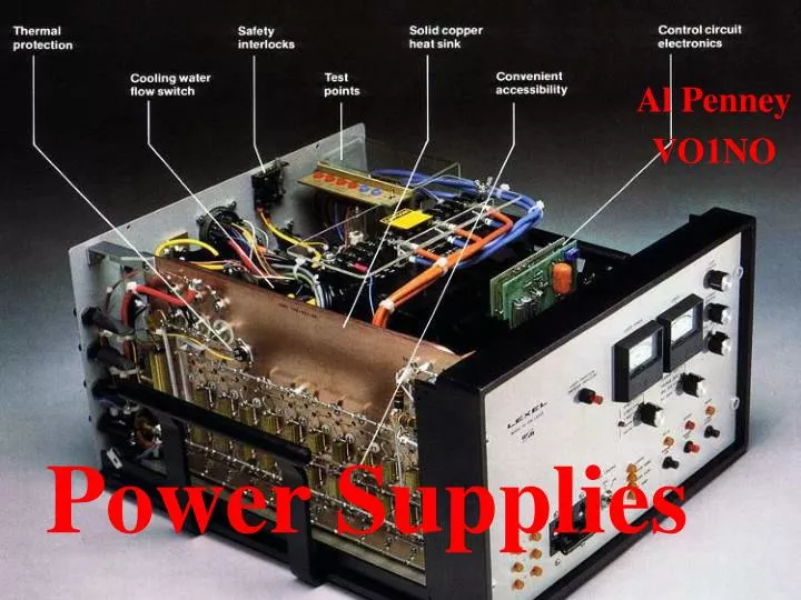
Power Supplies Al Penney VO1NO
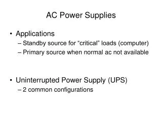
Power Requirements • Most Amateur Radio gear today requires 13.8 volts DC (Direct Current). • Wall outlets provide 120 volts AC (Alternating Current) however. • To convert AC to DC at the proper voltage, we use Power Supplies.
Typical Power Requirements • TS-870S HF Transceiver 20.5 amps • FT-7800R Dual Band FM Txcvr 8.5 amps • FT-100 HF/VHF/UHF Transceiver 22.0 amps • IC-7600 HF/6M Transceiver 23.0 amps
Power Supply Requirements • Voltage must be raised or lowered to the desired value. • Voltage must be changed from AC to DC. • The DC that is produced will contain a lot of ripple, and must be filtered. • The DC voltage must be regulated so that it remains fairly constant.
Power Supply Block Diagram Input Transformer Rectifier Filter Output Regulator
Changing the Voltage • A transformer is used to step the voltage up or down. • The ratio of turns in the primary and secondary windings determine the amount of voltage change: Primary Voltage # Turns Primary winding Secondary Voltage # Turns Secondary winding =
Example • Input voltage is 120 VAC. You require an output voltage of 13.8 VAC. The Primary winding has 240 turns. How many turns does the Secondary winding need?
Example (2) Primary Voltage # Turns Primary winding Secondary Voltage # Turns Secondary winding =
Example (3) Primary Voltage # Turns Primary winding Secondary Voltage # Turns Secondary winding • 120 / 13.8 = 240 / Tsec • Tsec = =
Example (4) Primary Voltage # Turns Primary winding Secondary Voltage # Turns Secondary winding • 120 / 13.8 = 240 / Tsec • Tsec = 240 x 13.8 / 120 =
Example (5) Primary Voltage # Turns Primary winding Secondary Voltage # Turns Secondary winding • 120 / 13.8 = 240 / Tsec • Tsec = 240 x 13.8 / 120 • Tsec = =
Example (6) Primary Voltage # Turns Primary winding Secondary Voltage # Turns Secondary winding • 120 / 13.8 = 240 / Tsec • Tsec = 240 x 13.8 / 120 • Tsec = 27.6 turns, rounded to 28 turns =
Power Rating of the Transformer • Determined by the size of the core and the diameter of the wire. • Power rating usually stamped on the side of the transformer, and is expressed in Volt-Amperes (abbreviated VA). • Power = Voltage x Current • Calculate power requirements of the equipment using the power supply and compare it with the Power rating of the transformer.
Power Rating Example • Radio draws 20 amps at 13.8 VDC. • Transformer rated at 250 VA. • Is the transformer big enough for the job?
Power Rating Example (2) • Power = Voltage x Current • Power =
Power Rating Example (3) • Power = Voltage x Current • Power = 13.8 VDC x 20 Amps =
Power Rating Example (4) • Power = Voltage x Current • Power = 13.8 VDC x 20 Amps = 276 Watts
Power Rating Example (5) • Power = Voltage x Current • Power = 13.8 VDC x 20 Amps = 276 Watts • Transformer is rated at 250 VA, so….
Power Rating Example (6) • Power = Voltage x Current • Power = 13.8 VDC x 20 Amps = 276 Watts • Transformer is rated at 250 VA, so…. • The transformer is NOT big enough for the task!
Isolation • The load attached to the transformer is not physically connected to the primary, as the windings are insulated. • Much consumer equipment is powered without transformers to keep costs down. • As a result the chassis is directly connected to one side of the AC line, and must therefore be enclosed in an insulated cabinet for safety reasons. • Amateur gear must be capable of interconnection, and so such construction is unacceptable for us. • Fuse in the AC line provides additional safety.
Rectification • The process by which AC is converted to DC is called Rectification. • Broadly classified as either: • Half Wave: rectify only the positive or negative half of each AC cycle; or • Full Wave: rectify both halves of the AC cycle.
Half Wave Rectification • Half Wave rectification only passes half of the energy thru to the output. • Resulting DC is very rough and needs heavy filtering. • If current requirements are small however, it provides a simple and low-cost solution.
Full Wave RectificationCenter-Tap Transformer • Passes all the energy thru to the output. • This method requires a center tap however. • The diodes work alternately, handling the full current load but only for half the time. • Essentially this is two half wave rectifiers operating on opposite polarities of the AC cycle. • An advantage of this method is that the resulting DC ripple frequency is 120 Hz (twice 60 Hz), making it easier to filter.
Full Wave RectificationWithout a Center Tap Transformer • This method eliminates the requirement for a center tap transformer. • It uses a Full Wave Bridge Rectifier. • Note the polarity of the diodes – two will conduct and two will not conduct on each half-cycle.
Filtering the DC • Straight out of the rectifier stage, the DC pulsates, causing severe hum on transmitted and received signals, as well as a host of other problems. • This fluctuating DC must be “smoothed out” by a filter. • The most effective way to do this is by using a capacitor across the output of the power supply.
Voltage Output Straight from Rectifier stage After filtering by the Capacitor
Filtering • The capacitor stores energy when the pulsating DC is high, and delivers it to the load when the DC voltage falls. • Ensure that the capacitor has a working voltage of at least 1.5 times that of the power supply. • “AC hum” is a sign that the filter capacitor is failing. • A “bleeder resistor” should be placed across the terminals of the capacitor to safely discharge it when the supply is turned off. • When extra filtering is required, additional capacitors and inductors are used.
Regulating Voltage and Current • The output voltage will tend to drop when a load is applied. • A regulator circuit will ensure that the voltage stays constant when a heavy demand is placed on the supply. • It works by acting as an electronically variable resistor between the filter and the output. As DC output voltage rises, resistance increases, and vice versa. • Do not try to exceed the maximum output of the power supply!
Zener Diodes • A Zener Diode is a type of diode that permits current in the forward direction like a normal diode, but also in the reverse direction if the voltage is larger than the breakdown voltage known as the"Zener voltage". • Important components of voltage regulation circuits. • When connected in parallel with a variable voltage source so that it is reverse biased, a Zener diode conducts when the voltage reaches the diode's reverse breakdown voltage. From that point on, the relatively low impedance of the diode keeps the voltage across the diode at that value.
Chirp • A poorly regulated power supply can cause the transmitter frequency to vary as the radio is keyed. • When this happens with a CW signal, the resulting frequency change is called a chirp. • Check the regulation of your power supply if you receive a report of chirp.
Monitoring the Output • Good commercial power supplies include a voltmeter and ammeter to monitor voltage and current. • Homebrew power supplies should also incorporate voltmeters and ammeters.
Monitoring the Output • Voltmeters are connected in parallel with (ie: across) the output of the power supply. Ensure that the meter’s polarity is correct. • Ammeters are usually placed in series with the positive output terminal, but can also be placed in the negative return line. + A + From Filter stage V Output
Switching Power Supplies • Switching Power Supplies switch a power transistor between saturation(full on) and cutoff (completely off) with a variable duty cyclewhose average is the desired output voltage. • Switching rate is in the range of tens to hundreds of kHz, which can cause electronic “noise” on receivers. • Advantage is that they are much lighter and smaller than conventional power supplies, but they are more complex. • In widespread use nowadays.