Download

1 / 77
1.04k likes | 2.72k Views
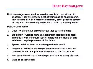
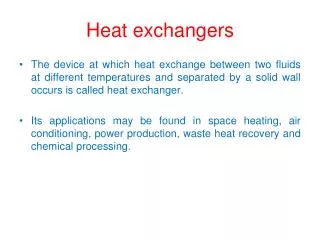
HEAT TRANSFER, HEAT EXCHANGERS, CONDENSORS AND REBOILERS, AIR COOLERS. Reyad Awwad Shawabkeh Associate Professor of Chemical Engineering King Fahd University of Petroleum & Minerals Dhahran, 31261 Kingdom of Saudi Arabia. Contents HEAT TRANSFER LAW APPLIED TO HEAT EXCHANGERS 2

E N D
HEAT TRANSFER, HEAT EXCHANGERS, CONDENSORS AND REBOILERS, AIR COOLERS ReyadAwwadShawabkeh Associate Professor of Chemical Engineering King Fahd University of Petroleum & Minerals Dhahran, 31261 Kingdom of Saudi Arabia
Contents • HEAT TRANSFER LAW APPLIED TO HEAT EXCHANGERS 2 • Heat Transfer by Conduction 3 • The Heat Conduction Equation 9 • Heat Transfer by Convection 12 • Forced Convection 12 • Natural Convection 14 • Heat Transfer by Radiation 15 • Overall heat transfer coefficient 18 • Problems 22 • DESIGN STANDARDS FOR TUBULAR HEAT EXCHANGERS 23 • Size numbering and naming 23 • Sizing and dimension 27 • Tube-side design 32 • Shell-side design 33 • Baffle type and spacing 33 • General design consideration 35 • THERMAL AND HYDRAULIC HEAT EXCHANGER DESIGN 37 • Design of Single phase heat exchanger 37 • Kern’s Method 45 • Bell’s method 49 • Pressure drop inside the shell and tube heat exchanger 57 • Design of Condensers 65 • Design of Reboiler and Vaporizers 72 • Design of Air Coolers9 85 • MECHANICAL DESIGN FOR HEAT EXCHANGERS10 88 • Design Loadings 88 • Tube-Sheet Design as Per TEMA Standards 90 • Design of Cylindrical shell, end closures and forced head 91 • References 95
Heat Transfer by Conduction W/m.K W/m2
Calculate the heat flux within a copper rod that heated in one of its ends to a temperature of 100 oC while the other end is kept at 25 oC. The rode length is 10 m and diameter is 1 cm. Example
Example An industrial freezer is designed to operate with an internal air temperature of -20 oC when external air temperature is 25 oC. The walls of the freezer are composite construction, comprising of an inner layer of plastic with thickness of 3 mm and has a thermal conductivity of 1 W/m.K. The outer layer of the freezer is stainless steel with 1 mm thickness and has a thermal conductivity of 16 W/m.K. An insulation layer is placed between the inner and outer layer with a thermal conductivity of 15 W/m.K. what will be the thickness of this insulation material that allows a heat transfer of 15 W/m2 to pass through the three layers, assuming the area normal to heat flow is 1 m2?
The Heat Conduction Equation Rate of heat conduction into control volume Rate of heat generation inside control volume Rate of heat conduction out of control volume Rate of energy storage inside control volume = + +
Reynolds and Prandtl Numbers Re < 2100 Laminar flow Re > 2100 Turbulent flow Values of Prandtl number for different liquids and gases
Flow through a single smooth cylinder This correlation is valid over the ranges 10 < Rel < 107 and 0.6 < Pr < 1000 where
Flow over a Flat Plate Re < 5000 Laminar flow Re > 5000 Turbulent flow
Heat Transfer by Radiation q = ε σ (Th4 - Tc4) Ac Th = hot body absolute temperature (K) Tc = cold surroundings absolute temperature (K) Ac = area of the object (m2) σ= 5.6703 10-8 (W/m2K4) TheStefan-Boltzmann Constant
Overall heat transfer coefficient For a wall For cylindrical geometry
DESIGN STANDARDS FOR TUBULAR HEAT EXCHANGERS • Size of heat exchanger is represented by the shell inside diameter or bundle diameter and the tube length • Type and naming of the heat exchanger is designed by three letters single pass shell The first one describes the stationary head type The second one refers to the shell type The third letter shows the rear head type TYPE AES refers to Split-ring floating head exchanger with removable channel and cover.
Removable cover, one pass, and floating head heat exchanger Removable cover, one pass, and outside packed floating head heat exchanger
Channel integral removable cover, one pass, and outside packed floating head heat exchanger
Removable kettle type reboiler with pull through floating head
Tube-side design Arrangement of tubes inside the heat exchanger
Shell-side design • one-pass shell for E-type, • split flow of G-type, • divided flow of J-type, • two-pass shell with longitudinal baffle of F-type • double split flow of H-type. types of shell passes
Shell-side design Shell thickness for different diameters and material of constructions
THERMAL AND HYDRAULIC HEAT EXCHANGER DESIGN Design of Single phase heat exchanger Design of Condensers Design of Reboiler and Vaporizers Design of Air Coolers
For counter current For co-current
two shell passes; four or multiples of four tube passes divided-flow shell; two or more even-tube passes
split flow shell, 2 tube pass cross flow heat exchanger
Shell and Tube design procedure • Kern’s Method This method was based on experimental work on commercial exchangers with standard tolerances and will give a reasonably satisfactory prediction of the heat-transfer coefficient for standard designs. • Bell’s method This method is designed to predict the local heat transfer coefficient and pressure drop by incorporating the effect of leak and by-passing inside the shell and also can be used to investigate the effect of constructional tolerance and the use of seal strip