Download
1 / 31
310 likes | 444 Views
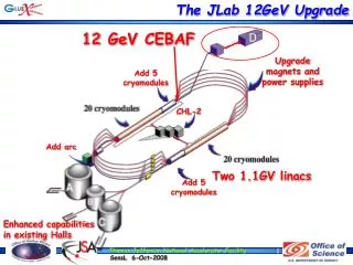
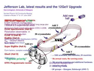
CEBAF in Hall B after the 12GeV upgrade. Yves Roblin. CLAS12 European workshop Paris March 7-11, 2011. OUTLINE. From 6 GeV To 12 GeV Top level parameters Beam specifications Double bend achromat Beam Halo Extraction scheme Current status Conclusion. From 6 GeV to 12 GeV.

E N D
CEBAF in Hall B after the 12GeV upgrade Yves Roblin CLAS12 European workshop Paris March 7-11, 2011
OUTLINE • From 6 GeV To 12 GeV • Top level parameters • Beam specifications • Double bend achromat • Beam Halo • Extraction scheme • Current status • Conclusion
From 6 GeV to 12 GeV HALLD ARC1 ARC2 ARC3 ARC4 ARC5 ARC6 ARC7 ARC8 ARC9 ARCA
Optimal ARC choices for 12GeV • Optimization for 6 GeV was aimed at preserving small dp/p (a few 10-5) • Arcs were achromatic and isochronous. • 12 GeV beam is dominated by Synchrotron radiation past Arc6 • Relax isochronous requirement and instead go for emittance minimization • Double Bend Achromat optics • Synchrotron radiation loss in ARCS compensated by adjusting dipole via trim coils. • S/R step ratio changed to accommodate ranges.
12GeV DBA optics 200 3 δ (m) Beta(m) -3 0 200 3 δ (m) Beta(m) Arc6 thru ArcA changed to DBA -3 0
Transverse Emittance* and Energy Spread† DBA option Damping Sync. Rad. * Emittancesare geometric † Quantities are rms
Beam line occupancy • R=4(beam + orbit) = 4beam + 2.4mm orbit <600 µm RMS Consistent with current operating practices
Extraction Scheme Current 12GeV scope is to deliver hall D And two beam A/C or A/B or B/C at two different passes However, upgrade to D+2 is being done. Will allow to: Deliver D beam + 2 other beams With the option of having 2 at 5 pass. Also possible to do A/B/C at 5 pass (no D)
Horizontally deflecting septa Horizontally deflecting Lambertson Horizontally deflecting RF cavities (499MHz, copper) Horizontally deflecting dipoles Scope Description New Relocated Modified 12 GeV Upgrade Elevation View Pass 1 Pass 2 Pass 3 Pass 4 Pass 5 Recirculation ARCS 12 GeV Upgrade Plan View Courtesy: Mike Spata
Upgrade to D+2 Addition of RF separators on Pass 5 to restore the capability to deliver 3 halls at 5 pass Or deliver Hall D + two halls at 5 pass Courtesy: Mike Spata
Changes to Hall B beamline(not including detectors) Quadrupoles upgraded, corrector upgraded QA QA QK QY C03,C04,C24 C05 -> C20 QA QR C22,23 QK: 30cm QA with 20A card QR: 35.56cm steel, 20A card QY:stronger version of QR, being developed.
Tuning of the beamline MQA2C01,MQA2C02 Match to fodo MQK2C03,MQK2C04 MQR2C09, MQR2C17 δy, δy' MQR2C21, MQK2C22MQY2C23,MQK2C24 Beam spot Well Defined independent knobs
Sensitivity to input parameters Before rematch After rematch Many input variations, with re -matching of the transport and beam spot. Beta’s varied by factor of 2 Alphas by +/1 All optics can be corrected within existing quadrupole range
Beam sizes in Hall B at 11 GeV WithinSpecs x < 400 μm y < 400 μm
Start to end simulations Beamline modeled with errors, multipoles, misalignments, apertures, … Full start to end simulation including extraction Use of LQCD clusters for massive halo studies (hallD) DBA optics Arc6 thru 9 Floor coordinates HallB Exit of injector
Beam spot tuning range Can cover beam spot size range from 200 to 800 µm sigma -100 100 10 % engineering margin *QY2C23 quad range actually taken as a QR and it is sufficient
Halo in hall B Estimated from studies done for Hall D Full scale simulation to be done with hall B collaboration Can use beam distributions has a seed for detector Monte-carlo simulations
Massively parallel ELEGANT simulations Using ELEGANT on the LQCD clusters 128 cpus, 50 minutes Jlab LQCD cluster Invaluable for validating 12GeV optics • Synchrotron radiation • Skew and normal multipoles • Apertures • Orbit coverage • Misalignments • Mis-powering Beam at RADIATOR in Hall D, DBA optics Simulation across the whole machine. 2Millions particles
Horizontal Beam Profile at HALLD Radiator Halo is 8E-6 << 5E-5 WithinSpecs
Beam gas scattering • Beam gas Bremsstrahlung • Inelastic scattering off atomic electrons • Thermal photons scattering • Elastic Scattering off Nuclei • Most of these proportional to 1/E2 4 times easier at 12 GeV
Conclusions 12 GeV CEBAF design is robust and has been reviewed many times User specifications will be met Detailed beamline layout (diagnostics, etc..) to bedetermined with hall B collaboration Engage with collaboration and start refining
APPENDIX. NOT SHOWN DURING TALK UNLESS NEEDED. CAN BE PRINTED.
Vertical clearance for separators Courtesy: Mike Spata