Download
1 / 23
230 likes | 324 Views
Images. P. P’. p. q. Image. Object. Mirror. Flat Mirror Images. Your eyes tell you where/how big an object is Mirrors and lenses can fool your eyes – this is sometimes a good thing. Place a point light source P in front of a mirror

E N D
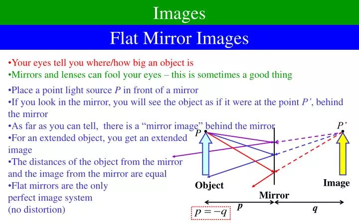
Images P P’ p q Image Object Mirror Flat Mirror Images • Your eyes tell you where/how big an object is • Mirrors and lenses can fool your eyes – this is sometimes a good thing • Place a point light source P in front of a mirror • If you look in the mirror, you will see the object as if it were at the point P’, behind the mirror • As far as you can tell, there is a “mirror image” behind the mirror • For an extended object, you get an extendedimage • The distances of the object from the mirrorand the image from the mirror are equal • Flat mirrors are the onlyperfect image system(no distortion)
Image Characteristics and Definitions h h’ p q Image Object Mirror • The front of a mirror or lens is the side the light goes in • The object distance p is how far the object is in front of the mirror • The image distance q is how far the image is in front of the mirror (or back for lenses) • Real image if q > 0, virtual image if q < 0 • The magnification M is how large the image is compared to the object • Upright if positive, inverted if negative
Spherical Mirrors X F V f • Typical mirrors for imaging are spherical mirrors – sections of a sphere • It will have a radius R and a center point C • We will assume that all angles involved are small • Optic axis:an imaginary line passing through the center of the mirror • Vertex: The point where the Optic axis meets the mirror • The paths of some rays of light are easy to figure out • A light ray through the center will come back exactly on itself • A ray at the vertex comes back at the same angle it left • Let’s do a light ray coming in parallel to the optic axis: • The focal point F is the place this goes through • The focal length f = FV is the distance to the mirror • A ray through the focal pointcomes back parallel C R
Ray Tracing: Mirrors F F • Any ray coming in parallel goes through the focus • Any ray through the focus comes out parallel • Any ray through the center comes straight back • Let’s use these rules to find the image: • Do it again, but harder • A ray through the center won’t hit the mirror • So pretend it comes from the center • Similarly for ray through focus • Trace back to see where they came from C C
Spherical Mirrors: Finding the Image Q h’ Y • The ray through the center comes straight back • The ray at the vertex reflects at same angle it hits • Define some distances: • Some similar triangles: X h V P C • Cross multiply • Divide by pqR: • Magnification • Since image upside down, treat h’as negative
Convex Mirrors: Do they work too? F • Up until now, we’ve assumed the mirror is concave – hollow on the side the light goes in • Like a cave • A convex mirror sticks out onthe side the light goes in • The formulas still work, butjust treat R as negative • The focus this time will be on the other side of the mirror • Ray tracing still works C Summary: • A concave mirror has R > 0; convex has R < 0, flat has R = • Focal length is f = ½R • Focal point is distance f in front of mirror • p, q are distance in front of mirror of image, object • Negative if behind
Mirrors: Formulas and Conventions • A concave mirror has R > 0; convex has R < 0, flat has R = • Focal length is f = ½R • Focal point is distance f in front of mirror • p, q are distance in front of mirror of object/image • Negative if behind • For all mirrors (and lenses as well): • The radius R, focal length f, object distance p, andimage distance q can be infinity, where 1/ = 0, 1/0 =
Sample problem 5 cm 10 cm • You can use more than one mirror to make images of images • Just use the formulas logically Light from a distant astronomical source reflects from an R1 = 100 cm concave mirror, then a R2 = 11 cm convex mirror that is 45 cm away. Where is the final image? 45 cm
Refraction and Images q 1 Q h’ 2 Y • Now let’s try a spherical surface between two regions with different indices of refraction • Region of radius R, center C, convex in front: • Two easy rays to compute: • Ray towards the center continues straight • Ray towards at the vertex follows Snell’s Law • Small angles, sin tan • A similar triangle: R X n1 h C P p n2 • Cross multiply: • Divide by pqR: • Magnification:
Comments on Refraction • R is positive if convex (unlike reflection) • R > 0 (convex), R < 0 (concave), R = (flat) • n1 is index you start from, n2 is index you go to • Object distance p is positive if the object in front (like reflection) • Image distance q is positive if image is in back (unlike reflection) • We get effects even for a flat boundary, R = • Distances are distorted: R X n1 q h Q P p n2 2 Y • No magnification:
Double Refraction and Thin Lenses p n1 n2 n1 • Just like with mirrors, you can do double refraction • Find image from first boundary • Use image from first as object for second • We will do only one case, a thin lens: • Final index will match the first, n1 = n3 • The two boundaries will be very close n1 n2 n3 • Where is the final image? • First image given by: • This image is the object for the second boundary: • Final Image location: • Add these:
Thin Lenses (2) • Define the focal length: • This is called lens maker’s equation • Formula relating image/object distances • Same as for mirrors • Magnification: two steps • Total magnification is product • Same as for mirrors
Using the Lens Maker’s Equation • If you are working in air,n1 = 1, and we normally calln2 = n. • By the book’s conventions, R1, R2 are positive if they are convex on the front • You can do concave on the front as well, if you use negative R • Or flat if you set R = • If f > 0, called a converging lens • Thicker in middle • If f < 0, called a diverging lens • Thicker at edge • If you turn a lens around, its focal length stays the same
Ray Tracing with Converging Lenses F F f f • Unlike mirrors, lenses have two foci, one on each side of the lens • Three rays are easy to trace: • Any ray coming in parallel goes through the far focus • Any ray through the near focus comes out parallel • Any ray through the vertex goes straight through • Like with mirrors, you sometimes have to imagine a ray coming from a focus instead of going through it • Like with mirrors, you sometimes have to trace outgoing rays backwards to find the image
Ray Tracing with Diverging Lenses F F f f • With a diverging lens, two foci as before, but they are on the wrong side • Still can do three rays • Any ray coming in parallel comes from the near focus • Any ray going towards the far focus comes out parallel • Any ray through the vertex goes straight through • Trace purple ray back to see where it came from
Lenses and Mirrors Summarized • The front of a lens or mirror is the side the light goes in • Variable definitions: • f is the focal length • p is the object distance from lens • q is the image distance from lens • h is the height of the object • h’ is the height of the image • M is the magnification • Other definitions: • q > 0 real image • q < 0 virtual image • M > 0 upright • M < 0 inverted
Imperfect Imaging F • With the exception of flat mirrors, all imaging systems are imperfect • Spherical aberration is primarily concerned with the fact that the small angle approximation is not always valid F • Chromatic Aberration refers to the fact that different colors refract differently • Both effects can be lessened by using combinations of lenses • There are other, smaller effects as well
Cameras q • Real cameras use a lens or combination of lenses for focusing • The aperture controls how much light gets in • The shutter only lets light in for the right amount of time • The CCD array detects the light • Focusing: CCD must be at distance q: • Adjust position of lens for focus • Typically, p , q f • Exposure: • The more the object is magnified, the dimmer it is • The larger the area of the aperture, the more light • The ratio of the diameter to the focal length is called the f-number • The exposure time will be inversely proportional to Intensity Shutter Aperture Lens CCD Array
Eyes • Eyes use a dual imaging system • The Cornea contains water-like fluid that does most of the refracting • The Lens adds a bit more • The iris is the aperture • The eye focuses the light on the retina • Neither the cornea nor the lens moves • The shape (focal length) of the lensis adjusted by muscles • Over time, the lens becomes stiffand/or the muscles get weak • A healthy eye can normally focus on objects from 25 cm to • If it can’t reach , we saysomeone is nearsighted • If it can’t reach 25 cm, wesay someone is farsighted
Angulare Size and Angular Magnification h 0 d • To see detail of an object clearly, we must: • Be able to focus on it (25 cm to for healthy eyes, usually best) • Have it look big enough to see the detail we want • How much detail we see depends on the angular size of the object • Two reasons you can’t see objects in detail: • For some objects, you’d have to get closer than your near point • Magnifying glass or microscope • For others, they are so far away, you can’t get closer to them • Telescope Angular Magnification:how much bigger the angular size of the image is • Goal: Create an image of an object that has • Larger angular size • At near point or beyond (preferably )
The Simple Magnifier p h’ h -q F • The best you can do with the naked eye is: • d is near point, say d = 25 cm • Let’s do the best we can with one converging lens • To see it clearly, must have |q|d • Maximum magnification when |q| = d • Most comfortable when |q| = • To make small f, need a small R: • And size of lens smaller than R • To avoid spherical aberration, much smaller • Hard to get m much bigger than about 5
The Microscope Fe Fo • A simple microscope has two lenses: • The objective lens has a short focal length and produces a large, inverted, real image • The eyepiecethen magnifies that image a bit more • Since the objective lens can be small, the magnification can be large • Spherical and other aberrations can be huge • Real systems have many more lenses to compensate for problems • Ultimate limitation has to do with physical, not geometric optics • Can’t image things smaller than the wavelength of light used • Visible light 400-700 nm, can’t see smaller than about 1m
The Telescope 0 • A simple telescope has two lenses sharing a common focus • The objective lens has a long focal length and produces an inverted, real image at the focus (because p = ) • The eyepiecehas a short focal length, and puts the image back at (because p = f) fe fo F • Angular Magnification: • Incident angle: • Final angle: • The objective lens is made as large as possible • To gather as much light as possible • In modern telescopes, a mirror replaces the objective lens • Ultimately, diffraction limits the magnification (more later) • Another reason to make the objective mirror as big as possible