Download
1 / 28
290 likes | 421 Views
Building an Analysis Model of the System Under Development. Developing your design from the product specifications: Remember there is probably not a UNIQUE GOOD DESIGN for a given set of specifications But there are many BAD designs

E N D
Developing your design from the product specifications: Remember there is probably not a UNIQUE GOOD DESIGN for a given set of specifications But there are many BAD designs The goal of the design stage is to come up with a good design and to avoid bad design choices We will use some of the UML tools to explore the design and test out our design choices with respect to the specifications we are given, before we invest time and energy in actual coding.
Question: How do you start an OO design? • --components? • --objects? • --how will they interact? • Answer: One common method is to start with components, along with any design patterns which can be identified. • In general: • design is an iterative process • all team members should take an active part in exploring possible designs • simple designs are preferable to complex designs--but it may take several iterations to develop a simple design which meets the project requirements • As explained previously, we will use a subset of UML to do the project design.
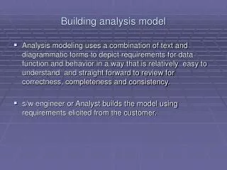
Analysis model (UML version): --functional model (use cases and scenarios) --analysis object model (static: class and object diagrams) --dynamic model (state and sequence diagrams) As system is analyzed, specifications are refined and made more explicit; if necessary, requirements are also updated
Figure 5-19 of text: an activity diagram for analyzing the system you are building:
Encounters an error condition Arms/disarms system Responds to alarm event “Review”: use case: Graphical description: Text description: Use case name Participating actors Flow of events Entry condition(s) Exit condition(s) Quality requirements Homeowner Accesses system via internet Sensors System administrator Reconfigures sensors and related system features Pressman, p. 163, Figure 7.3
“Review”: Use case writing guide (p. 137 of text): --each use case should be traceable to requirements --name should be a verb phrase to indicate user goal --actor names should be noun phrases --system boundary needs to be clearly defined --use active voice in describing flow of events, to make clear who does what --make sure the flow of events describes a complete user transaction ---if there is a dependence among steps, this needs to be made clear --describe exceptions separately --DO NOT describe the user interface to the system, only functions --DO NOT make the use case too long—use extends, includes instead --as you develop use cases, develop associated tests (for example, scenarios can suggest some good test cases, try to be as thorough as is reasonable in developing tests)
“Review”: Use case additions—simplifications of use case descriptions • A. Include: one use case includes another in its flow of events (cases A and B both include case C) • Extend: extend one use case to include additional behavior (cases D and E are extensions of case F) <<include>> A C B <<include>> <<extend>> D F E <<extend>>
“Review”: Use case additions • C. Inheritance: one use case specializes the more general behavior of another G and H specialize behavior of J) G J Authenticate with password authenticate H Authenticate with card
Class and object diagrams: Identify Objects from Use Case Specifications: USE ENDUSER’s TERMS AS MUCH AS POSSIBLE Entity objects: “things”, for example: --nouns (customer, hospital, infection) --real-world entities (resource, dispatcher) --real-world activities to be tracked (evacuation_plan) --data sources or sinks (printer) Boundary objects: system interfaces, for example: --controls (report(emergencybutton) --forms (savings_deposit_form) --messages (notify_of_error) Control objects: usually one per use case --coordinate boundary and entity objects in the use case Use the identified objects in a sequence diagram to carry out the use case
Other common types of classes which the developer can look for include: • tangible things, e.g., Mailbox, Document • system interfaces and devices, e.g., DisplayWindow, Input Reader • agents, e.g., Paginator, which computes document page breaks, or InputReader • events and transactions, e.g., MouseEvent,CustomerArrival • users and roles, e.g., Administrator, User • systems, e.g., mailsystem (overall), InitializationSystem (initializes) • containers, e.g., Mailbox, Invoice, Event • foundation classes, e.g., String, Date, Vector, etc. Common classes
Sequence Diagram Sequence Diagram: a sequence diagram also models dynamic behavior typically a sequence diagram shows how objects act together to implement a single use case messages passed between the objects are also shown sequence diagrams help to show the overall flow of control in the part of the program being modeled they can also be used to show: concurrent processes asynchronous behavior
Sequence Diagram--Syntax Objects in the sequence diagram are shown as boxes at the top below each object is a dashed vertical line--the object’s “lifeline” an arrow between two lifelines represents each message arrows are labeled with message names and can also include information on arguments and control information two types of control: condition, e.g., [is greaterthan zero] iteration, e.g., *[for all array items] “return” arrows can also be included
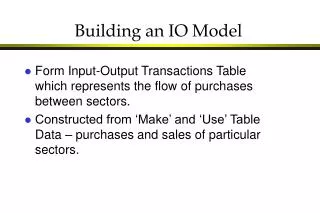
Useful object relationships • These diagrams represent the relationships between the classes in the system. These represent a static view of the system. • There are three basic types of relationship: • inheritance ("is-a") (NOT the same as use case inheritance) • aggregation ("has-a”) • association ("uses") • These are commonly diagrammed as follows: ER diagrams
manager employee ER diagram: is-a is-a: draw an arrow from the derived to the base class:
car tire 1 4 ER diagram--has-a has-a: draw a line with a diamond on the end at the "container" class. Cardinalities may also be shown (1:1, 1:n, 1:0…m; 1:*, i.e., any number > 0, 1:1…*, i.e., any number > 1): tire & car can exist independently—shared aggregation person arm is part of the person– composition aggregation arm 1 2
ER diagram--uses uses or association: there are many ways to represent this relationship, e.g., employs 1 company car gasstation * * * n employee 1 works for
CRC cards CRC cards: class--responsibilities--collaborators cards "responsibilities" = operators, methods "collaborators" = related classes (for a particular operator or method) Make one actual card for each discovered class, with responsibilities and collaborators on the front, data fields on the back. CRC cards are not really part of UML, but are often used in conjunction with it. The CRC card contains information about what is inside the class (data, structures, methods).
Class Mailbox Operations Relationships (Responsibilities) (Collaborators) get current message Message, Messagequeue play greeting ----------- Example (based on Horstmann, Practical Object-Oriented Development in C++ and Java): front back CRC card--example Class Mailbox Queue of new messages Queue of kept messages Greeting Extension number Passcode Note: Bruegge & Dutoit DO NOT include CRC cards—(they do show some internal information on their “class” boxes)—YOU NEED TO USE CRC CARDS, they provide more information
State Diagram State Diagram: another way of adding detail to the design--models dynamic behavior describes all the possible states a particular object can be in and how that object's state changes as a result of events that affect that object usually drawn for a single class to show behavior of a single object used to clarify dynamic behavior within the system, as needed
State Diagram--Properties A state diagram contains a "start" point, states, and transitions from one state to another. Each state is labeled by its name and by the activities which occur when in that state. Transitions can have three optional labels: Event [Guard] / Action. A transition is triggered by an Event. If there is no Event, then the transition is triggered as soon as the state activities are completed. A Guard can be true or false. If the Guard is false, the transition is not taken. An Action is completed during the transition.
State Diagram--Example Example: this state diagram example for an "order" in an order-processing system is from Fowler and Scott, UML Distilled (Addison-Wesley, 1997): start /get first item [not all items checked] /get next item [all items checked && all items available] Dispatching Checking initiate delivery check item [all items checked && some items not in stock] delivered item received [all items in stock] Delivered Waiting item received [some items not in stock]
Example—bank simulation (Horstmann) Horstmann, Mastering Object-Oriented Design in C++, Wiley, 1995 Teller 1 Teller 2 Customer 3 Customer 2 Customer 1 Teller 3 Teller 4
Bank Statistics Customer Bank Application Arrival Departure EventQueue Event Example—bank simulation (Horstmann), cont. An initial solution (Horstmann, p. 388):
Bank Statistics Customer Bank Simulation Arrival Departure EventQueue Event Example—bank simulation (Horstmann), cont. An improved solution (Horstmann, p. 391):
Bank Statistics Bank Statistics Customer Bank Customer Bank Application Simulation Arrival Arrival Departure Departure EventQueue EventQueue Event Event Comparison What simplifications have been made? Why?
Example: How would we use the tools described so far to design a “state-of-the art” vending machine? How would we develop test cases at each stage? Use cases? Class diagram? Sequence diagram? Classes / CRC cards?