Download
1 / 26
270 likes | 613 Views
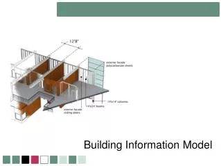
Analysis modeling fuses text and diagrams to illustrate data, function, and behavior requirements for software. It helps bridge the gap between system-level functionality and software design by depicting user scenarios, activities, and flow of data. Learn about domain analysis, essential rules of thumb, and elements like data modeling concepts. This guide emphasizes the importance of simplicity, avoiding unnecessary details, and providing value to stakeholders while highlighting object-oriented analysis techniques.

E N D
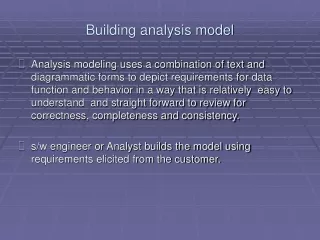
Building analysis model • Analysis modeling uses a combination of text and diagrammatic forms to depict requirements for data function and behavior in a way that is relatively easy to understand and straight forward to review for correctness, completeness and consistency. • s/w engineer or Analyst builds the model using requirements elicited from the customer.
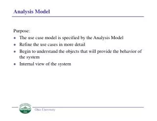
Requirements Analysis Requirements analysis allows the software engineer (an analyst or modeler ) to elaborate on basic requirements established during earlier requirement engineering tasks and build models that depict user scenarios, functional activities, problem classes and their relationships, system and class behavior and the flow of data as it is transformed. It provides the software designer with representation of information, function and behavior that can be translated to architectural, interface, and component level designs The analysis model and the requirements specification provide the developer and the customer with the means to assess quality once S/w is built.
Overall Objectives The analysis model must achieve three primary objectives: • To describe what the customer requires. • To establish a basis for the creation of a s/w design. • To define a set of requirements that can be validated once the s/w is built. The analysis model bridges the gap b/w a system-level description that describes overall system functionality as it is achieved by applying s/w, h/w and other system elements and a s/w design that describes s/w application, architecture ,user interface and component level structure.
Analysis Rules of Thumb Arlow and Neustadt suggest a no. of worthwhile rules of thumb that should be followed when creating the analysis model: • The model should focus on requirements that are visible within the problem or business domain. • Each element of the analysis model should add to an overall understanding of s/w requirements and provide insight into the information domain, function, and behavior of the system. • Delay consideration of infrastructure and other non-functional models until design. Ex: Database.
Minimize coupling throughout the system. It is important to represent relationships between classes and functions. • Be certain that the analysis model provides value to all stakeholders ( business people, s/w designer, QA people for planning acceptance tests) • Keep the model as simple as it can be. Don’t add additional diagrams when they provide no new information. Don’t use complete notational forms, when a simple list will do.
Domain Analysis • The “specific application domain “ can range from avionics to banking, from multimedia video games to s/w embedded within medical devices. • The role of the domain analyst is to discover and define reusable analysis patterns, analysis classes, and related information that may be used by many people working on similar but not necessarily the same applications. Sources of domain knowledge Technical literature Domain Analysis model Class taxonomies Domain analysis Existing applications Reuse standards Customer Surveys Functional models Expert advice Domain languages Current/future requirements
Analysis modeling approaches • One view of AM is structured analysis ,considers data and the processes that transform the data as separate entities • Data objects are modeled in a way that defines their attributes and relationships. • Processes that manipulate data objects are modeled in a manner that shows how they transform data as data objects flow through the system. • Second view is object oriented analysis , focuses on the definition of classes and the manner in which they collaborate with one another to effect customer requirements.
Analysis modeling leads to the derivation of each of the fallowing modeling Elements
Data modeling concepts • Data objects. it is a representation of composite information that must be understood by s/w. Ex: Dimension (width, height…) • it encapsulates data only there is no reference with in a data object to operations that act on data. Car
Data attributes it defines the properties of data objects and take one of the three different characteristics 1) name an instance of the data object 2) describe the instance 3) make reference to another instance in another table • Relationships Data objects are connected to one another in different ways. owns person car
Cardinality it is the specification of the no..of occurrences of one object that can be related to the the no. of occurrences of another object. (1:1,1:N,M:N relation ship) • Cardinality also defines the maximum no’ of occurrences of an object in a relation • but it does not provide an indication of whether or not a data object must participate in the relationship. • modality of a relationship is 0, if there is no explicit need for the relationship to occur or the relationship is optional, when it is 1 it is mandatory.
Object Oriented Analysis • The intent of object oriented analysis is to define all classes (and the relation ships ,behavior associated with them) that are relevant to the problem to be solved. • To accomplish a no. of tasks must occur • basic user requirements must be communicated b/w the customer and the s/w engineer. • classes must be identified. (i.e attributes and methods are defined) • a class hierarchy is defined • object – object relationship should be represented • object behavior must be modeled. • task 1 through 5 are reapplied iteratively until the model is complete. OOA builds class oriented model that relies on a understanding of OO concepts
Scenario based modeling • The success of the computer based system or product ism measured in many ways, user satisfaction resides at the top of the list. • If the s’w engineers understand how end-users want to interact with the system ,they can be better able to understand the requirements and build meaningful analysis and design models. • Analysis modeling with UML begins with creation of scenarios in the form of use cases, activity diagram and swim lane diagrams
Writing use cases • A use case captures the interaction that occurs b/w producers and consumers of information and the system itself. • Use-case describes a usage scenario from the point of view of a defined actor. • The first two requirements engineering tasks –inception, elicitation provide us information we need to begin writing use-cases • To begin developing a set of use-cases ,the functions or activities performed by specific actor are listed. • These may be obtained from a list of required system functions, through conversation with customer or end-users ,or by evaluating activity diagrams.
SafeHome Surveillance function These are the functions performed by the Home owner (actor) under the above sub system User scenario • Access camera surveillance via the internet • Select the camera to view . • Request thumbnails from all cameras • Display camera views in a PC window • Control pan and zoom for a specific camera • Selectively record camera output. • Replay camera output.
Use case • The home owner logs onto the safehome products website • The homeowner enters his id and password • The system displays all major function buttons. • The home owner selects surveillance button • The homeowner selects pick a camera • System display the floor plan of the house • Owner selects the camera icon from the floor plan • He selects the view button • System displays viewing window identified by the camera id • System displays video output at one frame per sec.
Developing activity diagram • The UML activity diagram supplements the use case by providing graphical representation of the flow of interaction with in a specific scenario • It is almost similar to a flow chart. • a rounded rectangle to represent a specific system function. • arrows to represent flow through the system. • Decision diamonds for branching decisions. • solid horizontal lines for parallel activities.
Activity diagram for access camera surveillance-display camera views function
Swimlane diagrams • Variation of activity diagram • Allows the modeler to represent the flow of activities described by the use case and at the same time indicates which actor or analysis class has responsibility for the action described by an activity rectangle
Flow oriented modeling • Data flow diagrams - It takes an input-process-output view of a system. - Data objects flow into the software, are transformed by processing elements, and resultant data objects flow out of the software - Data objects are represented by labeled arrows and transformations are represented by circles. • These are created in a hierarchical fashion. • First data flow model called level 0 DFD or context diagram represents overall system. • Subsequent diagrams refine context diagram representing increasing detail in each subsequent level.
Guide lines to follow 1. The level 0 DFD should depict the s/w or system as a single bubble. 2. Primary input and output should be carefully modeled. 3. Refinement should begin by isolating candidate process, data objects and data stores to be represented at the next level. 4. All arrows and bubbles should be labeled. 5. Information flow continuity must be maintained from level to level. 6. One bubble at a time should be refined.
Level1 DFD for safe-home security function Control Panel display alarm Telephone line