Download
1 / 11
170 likes | 1.03k Views
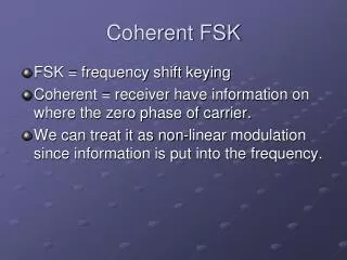
Power spectral density (PSD)… of ASK,PSK and FSK. Note that the bandwidth of FSK is higher than ASK or PSK . Conclusion is that ;polar signaling is the most efficient scheme from the point of view of the noise immunity.

E N D
Power spectral density (PSD)…of ASK,PSK and FSK • Note that the bandwidth of FSK is higher than ASK or PSK. • Conclusion is that ;polar signaling is the most efficient scheme from the point of view of the noise immunity. • The PSK, being polar, requires 3dB less power than ASK or FSK for the same noise immunity i.e. for the same error probability.
M-ary orthogonal pulses • Fig.3.33 shows just one possible M-ary scheme (multi-amplitude signaling). • There are other possible ways to structure M waveforms. For example we may use M orthogonal pulses φ1(t), φ2(t), …, φM(t), with the following property:-
M-ary orthogonal pulses Fig.3.34 shows one possible set of M orthogonal signals
M-ary orthogonal pulses… Cross correlation between any two rows is zero for e.g.. Hadamard matrix 4x4:- 1 1 1 1 1 -1 1 -1 1 1 -1 -1 1 -1 -1 1
More on quantization Block diagram of formatting and transmission of baseband signals Fig.2.2.
More on quantization… The ordinate in fig.2.16 is labeled with quantization levels and their code numbers. Each sample of the analog signal is assigned to the quantization level closest to the value of sample. Beneath the analog waveform x(t) are seen four representations of x(t) as follows:- The natural sample values, quantized sample values, the code numbers and the PCM sequence. Note that each sample is assigned to one of eight levels or a three bit PCM sequence.
More on quantization… Suppose that analog signal is a musical, which is sample at a Nyquist rate (fs ≥ 2fm). Also suppose that when we listen to the music in digital form, it’s quality is not good. What could we do to improve the fidelity? We know that process of quantization replaces the true signal with an approximation (i.e., adds quantization noise). Thus increasing the number of levels will reduce the quantization noise. If we double the number of levels to 16, what supposed to be the benifit?
More on quantization… Now, each sample will be represented by 4-bits, consequently we would have high data rates, improved signal quality or fidelity. In real time communication message must not be delayed, and bits must move faster. This is how one can generally obtain better fidelity at the cost of more transmission bandwidth Next Fig.2.18 compares the quantization of a strong versus a weak signal for uniform and non-uniform quantization. The staircase like waveforms represents approximation to the analog waveforms (after quantization distortion has been introduced.