Download
1 / 26
260 likes | 526 Views
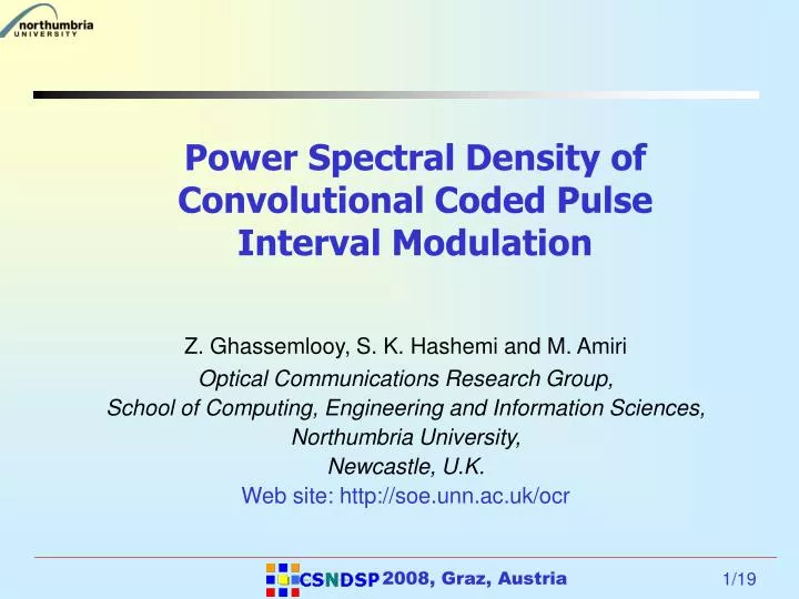
Power Spectral Density of Convolutional Coded Pulse Interval Modulation. Z. Ghassemlooy, S. K. Hashemi and M. Amiri Optical Communications Research Group, School of Computing, Engineering and Information Sciences, Northumbria University, Newcastle, U.K. Web site: http://soe.unn.ac.uk/ocr.

E N D
Power Spectral Density of Convolutional Coded Pulse Interval Modulation Z. Ghassemlooy, S. K. Hashemi and M. Amiri Optical Communications Research Group, School of Computing, Engineering and Information Sciences, Northumbria University, Newcastle, U.K. Web site: http://soe.unn.ac.uk/ocr 2008, Graz, Austria
Outline • Aims and Objectives - Motivations • Introduction • DPIM and Convolutional Coded DPIM • Power Spectral Density of CC-DPIM • Results • Conclusions 2008, Graz, Austria
Aims and Objective – Motivation • Carry out analysis for the power spectral density for the convolutional coded DPIM and investigate: • Bandwidth efficiency • DC component. • Compare the results with both the uncoded and coded DPIM 2008, Graz, Austria
Indoor Optical Wireless Communications Definition: • OWC is wireless transmission of light i.e. infrared radiation through the medium of the air. Some advantages are: • Higher bandwidth. • Unregulated bandwidth. • Immunity to electromagnetic interference. • High security compared with RF. • Absence of multipath fading (due to the use of IM/DD). • Complementary to RF. 2008, Graz, Austria
Modulation Techniques 2008, Graz, Austria
Frame 2 0 1 0 Frame 3 1 1 0 Frame 4 1 1 1 Frame 1 0 0 0 Information Digital Modulation Schemes DPIM 2008, Graz, Austria
Digital Pulse Interval Modulation • DPIM signal is defined : • p(t) - rectangular pulse shape, • Ts - slot duration • an - set of random variables representing a pulse/no pulse in the nth Ts • L = 2M, hence for M = 2, L = 4 slots. 2008, Graz, Austria
DPIM - Convolutional Coding • Linear block codes like Hamming code, Turbo code and Trellis coding are difficult (if not impossible ) to apply in PIM because of variable symbol length. • Hence, Convolutional coding - since it acts on the serial input data rather than the block. 2008, Graz, Austria
Convolutional Coding • Defined as (n,k,K), where k and n are the input (1) and output bits (i.e. 2), and K is the memory element. • Code rate is defined as k/n = 1/3. • Constraint length (K)=3; • The Generator Function: • G0 = [111] • G1 = [101] 2008, Graz, Austria
Convolutional Coded DPIM Average symbol length of code data: P[.] - probability function and . For L-DPIM and For CC-DPIM symbol length Lave = L + 5 2008, Graz, Austria
DPIM - Convolutional Coding • 2 empty slots / symbol - to ensure that the memory is cleared after each symbol. • Trellis path is limited to 2. 2008, Graz, Austria
DPIM - Decoder • Viterbi ‘Hard ‘ decision decoding • The Chernoff upper bond on the error probability is: where Pse is the slot error probability of uncoded DPIM. It is also possible not use Viterbi algorithm instead one can use a simple look-up table. 2008, Graz, Austria
Power Spectral Density • Generally signals can be divided into two models: • DeterministicModel - No uncertainty about signal’s time dependent behaviour at any instance of time. • Random or StochasticModel – Uncertain about signal’s time-dependent behaviour at any instance of time. However certain on the statistical behaviour of the signal on overall. • Power of Random Signal • Deterministic signals - Instantaneous power is x2(t). • Random signals – There is no single number to associate with the instantaneous power i.e. x2(t) is a random variable for each time. The expected instantaneous power of x2(t) need to obtained. 2008, Graz, Austria
PSD of CC-DPIM • A DPIM pulse train may be expressed as [12]: which is cyclostationary, where p(t) is the rectangular pulse shape, Ts is the slot duration and for all n is a set of random variables that represent the presence or absence of a pulse in the nth time slot. • xc(t) can be stationarized with the introduction of a continuous variable to give xs(t) = xc(t + ), where is equally distributed over [0, Ts] and is independent of an. The distribution of stationarization depends on the length probabilities given as: • . 2008, Graz, Austria
PSD of CC-DPIM • The general expression for the spectral distribution expressed by the spectral density is given as: Where • T is the input period of the {an} (the sequence !!), • P(f) is the Fourier transform of p(t), the rectangular pulse shape • |P(f)|2= T2Sinc2(fT) 2008, Graz, Austria
PSD of CC-DPIM (Contd.) • The continuous Spectrum of the CC-DPIM Sequence {an}is evaluated as: Where z = ei2Πu, is the greatest common divisor. • The Discrete part of the spectrum is defined as: Where 2008, Graz, Austria
PSD of CC-DPIM (Contd.) , 2008, Graz, Austria
PSD of CC-DPIM - Simulation • 8-CC-DPIM using (3-7), • Pulse shape p(t) - rectangular with 100% duty cycle. 2008, Graz, Austria
Results (1) DC level Clock (slot) PSD of 8-CC-DPIM with 100% pulse duty cycle against the normalised frequency: (a) predicted, and (b) simulated 2008, Graz, Austria
Results (2) DC level Clock (slot) PSD of 8-CC-DPIM with 50% pulse duty cycle against the normalised frequency: (a) predicted, and (b) simulated 2008, Graz, Austria
Results (1&2) - Observation • Slot (clock) component - Phase locked loop to recover it at the receiver. • The nulls at normalised frequencies (fT)0 = ±1, ±2,… are poles on the unit circle. • It is followed by two symmetrically close poles on both sides at (fT)0 = ±1.5. • With information on nulls and poles, filter H(z) can be implemented as an Auto Regressive Moving Average (ARMA) filter. • DC level – may result in the baseline wander effect due to high-pass filtering of the ambient light. 2008, Graz, Austria
Results (3)- Spectral Comparison High DC component 2008, Graz, Austria
Results (4) - Slot Error Rates • Higher bit resolution • provides better • performance ( at the • expense of bandwidth) • The code gain is 0.6 • higher for bit • resolution of 5 • compared to 3. 2008, Graz, Austria
8 , 16 , 32 - DPIM with one guard band @ R = 100 Mbps Uncoded 8 - DPIM R Coded Upper E Bound 8 - DPIM P , Uncoded 32 - DPIM r o r r Coded Upper e t Bound 32 - DPIM e k c Uncoded a P 16 - DPIM f o Coded Upper y t i Bound 16 - DPIM l i b a b o r P - 2 - 1 0 1 2 3 4 5 6 7 8 Electrical SNR ( dB ) Packet Error Rates - 4 10 - 6 10 - 8 10 - 10 10 - 12 10 2008, Graz, Austria
Conclusions • PSD of CC-DPIM has been derived analytically based on the stationarisation of variable length word sequence. • Close match between predicted and simulated results. • Clock components can used for synchronisation. • DCPIM > DCPPM, more susceptible to baseline wander • Convolutional coding has improved PER performance of DPIM scheme. 2008, Graz, Austria
Thank You! 2008, Graz, Austria