Download
1 / 16
170 likes | 415 Views
Lower Limits To Specific Contact Resistivity. Depts. of 2 Materials and 3 ECE, University of California, Santa Barbara, CA. Ashish Baraskar 1 , Arthur C. Gossard 2,3 , Mark J. W. Rodwell 3 1 GLOBALFOUNDRIES, Yorktown Heights, NY.

E N D
Lower Limits To Specific Contact Resistivity Depts. of 2Materials and 3ECE, University of California, Santa Barbara, CA Ashish Baraskar1, Arthur C. Gossard2,3, Mark J. W. Rodwell3 1GLOBALFOUNDRIES, Yorktown Heights, NY 24th International Conference on Indium Phosphide and Related Materials Santa Barbara, CA
Ohmic Contacts: Critical for nm & THz Devices Scaling laws to double bandwidth Ls/d Lg Intel 32 nm HKMG IEDM 2009 THz HBT: Lobisser ISCS 2012
Ohmic Contacts: Critical for nm & THz Devices Scaling laws to double bandwidth Ls/d Lg Intel 32 nm HKMG IEDM 2009 THz HBT: Lobisser ISCS 2012
Ultra Low-Resistivity Refractory Contacts Schottky Barrier is about one lattice constant what is setting contact resistivity ? what resistivity should we expect ?
Landauer (State-Density Limited) Contact Resistivity momentum velocity density current conductivity G valley L, X, D valleys
Landauer (State-Density Limited) Contact Resistivity momentum velocity density current conductivity G valley L, X, D valleys
About this work Scope • Analytical calculation of minimum feasible contact resistivities to n-type and p-type InAs and In0.53Ga0.47As. Assumptions • Conservation of transverse momentum and total energy across the interface • Metal E-k relationship treated as a single parabolic band • Band gap narrowing due to heavy doping neglected for the semiconductor
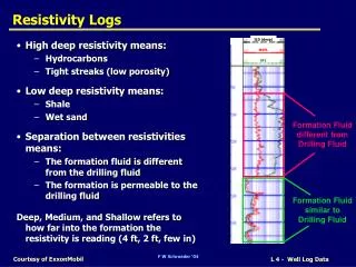
Potential Energy Profile • Schottky barrier modified by image forces • Modeled potential barrier: piecewise linear approximation • introduced to facilitate use of Airy functions for calculating transmission probability
Calculation of Contact Resistivity Current density, J z : transport direction ksx, ksyksz : wave vectors in the semiconductor vsz : electron group velocity in z direction T : interface transmission probability fs and fm : Fermi functions in the semiconductor and the metal Contact Resistivity, ρc
Results: Zero Barrier Contacts, Landauer Contacts Step potential energy profile Step Potential Barrier: interface quantum reflectivity, resistivity >Landauer Parabolic vs. non-parabolic bands: differing Efs-Ecs → differing interface reflectivity Landauer resistivity lower in Si than in Γ-valley semiconductorfs multiple minima, anisotropic bands
Results: InGaAs Assumes parabolic bands At n = 5×1019cm-3 doping, ΦB=0.2 eV measured resistivity 2.3:1 higher than theory Theory is 3.9:1 higher than Landauer In-situ contacts • References: • Jain et. al., IPRM, 2009 • Baraskar et al., JVST B, 2009 • Yeh et al., JJAP, 1996 • Stareev et al., JAP, 1993
Results: N-InAs n-InAs Assumes parabolic bands At n = 1020cm-3 doping, ΦB=0.0 eV measured resistivity 1.9:1 higher than theory Theory is 3.6:1 higher than Landauer In-situ contacts • References: • Baraskar et al., IPRM, 2010 • Stareev et al., JAP, 1993 • Shiraishi et al., JAP, 1994 • Singisetti et al., APL, 2008 • Lee et al., SSE, 1998
Results: P-InGaAs p-In0.53Ga0.47As Assumes parabolic bands Theory and experiment agree well. At n = 2.2×1020cm-3 doping, ΦB=0.6 eV theory is 13:1 higher than Landauer → Tunneling probability remains low. In-situ contacts • References: • Chor et al., JAP, 2000 • Baraskar et al., ICMBE, 2010 • Stareev et al., JAP, 1993 • Katz et al., APL, 1993 • Jain et al., DRC, 2010 • Jian et al., Matl. Eng., 1996
Conclusions Correlation of experimental Contact resistivities with theory excellent for P-InGaAs ~4:1 discrepancy for N-InGaAs, N-InAs N-contacts are approaching Landauer Limits theory vs. Landauer: 4:1 discrepancy tunneling probability is high
Transmission Probability, T Potential energy in various regions
(15) Transmission Probability, T Solutions of Schrodinger equation in various regions and are the Airy functions Transmission probability is given by .