Download
1 / 20
211 likes | 384 Views
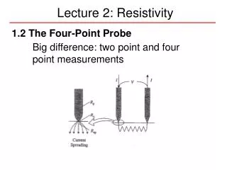
Resistivity - resistance. The applied voltage or current can cause heating of the material, which can change its resistivity. Even if heating of the sample is not a problem, Ohm’s law is not always obeyed.

E N D
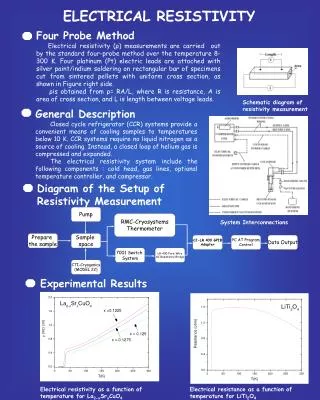
The applied voltage or current can cause heating of the material, which can change its resistivity. Even if heating of the sample is not a problem, Ohm’s law is not always obeyed. A critical check of a four-point measurement is to reverse the leads and remeasure the resistance. The most difficult part of making resistivity measurements is often making good electric contacts to the sample. The measurement system should be calibrated before measuring any material samples. Calibration procedures are usually described in the equipment manuals. The input resistance (or “impedance”) of the voltmeter should be at least 10 0000 higher than the resistance of the sample bar. The input impedance is usually listed in the equipment specifications. Note that some voltmeters and electrometers have a sufficiently high impedance between either of the inputs and ground, but not between the two inputs. In this case, it is necessary to use two voltmeters/electrometers (each with one input connected to ground and the other input connected to the sample bar)
In the “shunted T” network presented in Figure 14.8b, the state of balance (i.e., the minimal voltage v0 value) is achieved by tuning the multiloop LCR circuit to parallel resonance. The circuit analysis [7] is based on the “star-delta” transformation of the CrRrCr element loop and leads to the relations for L and R values: Up to 100Mhz