Download
1 / 14
160 likes | 339 Views
MPEG-1 Multiplexing. Nimrod Peleg Update: Nov. 1999. Multiplex Organization. System layer: Audio and Video encoders deliver Elementary Streams (ES), from the “ Compression Layer ”. Each ES carries Access Units (AU), which are the coded representations of Presentation Units (PU).

E N D
MPEG-1 Multiplexing Nimrod Peleg Update: Nov. 1999
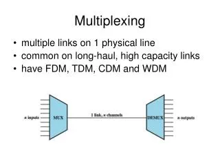
Multiplex Organization • System layer: • Audio and Video encoders deliver Elementary Streams (ES), from the “Compression Layer”. • Each ES carries Access Units (AU), which are the coded representations of Presentation Units (PU). • These streams, have to be combined in an organized manner (with additional information) to allow correct decoding. • “Private Data” streams also packed !
Decoder Missions • Separation of coded bit-stream into basic AU. • Synchronization of picture and sound. • Selection of the particular components of interest (done by the user). • Part I of MPEG-1 defines the rules of system layer, grouping video, audioand privatedata ES into a single bit-stream.
System Layer Functions • Packetization of multiple streams into one. • Addition of time stamps on ES for Synchronization at playback. • Initialization and management of the required buffers.
System Target Decoder • The system layer should also indicate the necessary resources required for the decoding the bit-stream. • One important example is the size of buffers needed in the decoder for each individual ES. • This is done using a theoretical reference decoder known as System Target Decoder (STD).
Packetized Elementary Stream Each ES is cut into packets to form a PES, starting with packet header and followed by data. Structure of MPEG1 packet: Start_code_prefix start code (00 00 01 Hex) 24 b Stream_id PES type (4b) and number (4b) 8 b Packet_length number of bytes to follow these 2 16 b Stuffing_bytes Optional stuffing 0 to 16x8 B
Structure of MPEG1 packet (cont’d) Start_STD bits 01: begin STD_buffer field 2 b STD_buffer_scale buffer size unit (0:128B,1:1024B 1 b STD_buffer_size in multiples of 128 or 1024 B 13 b PTS (optional) Presentation time stamp 40 b 4 code bits + 33 time bits + 3 marker bits DTS (optional) Decoding time stamp 40 b 4 code bits + 33 time bits + 3 marker bits Packet_data_byte Data (N=packet_length less the 6 following fields) Nx8 b
Some explanations... • Start code: 32b, including 4 for type (audio, video , private), and 4 for id number of the ES from which it comes. • Packet length: 16b, hence maximum length of 64KB • Buffer size: required by STD for decoding. • DTS: Decoding time of 1st AU of the packet. • PTS: The time at which the corresponding PU should be presented (displayed or made audible)
Time Stamps • Used for audio and video synchronization. • Sent frequently :maximum interval of 0.7Sec between consecutive stamps of a PES. • Time stamps are coded with 33 bits, which represent absolute time, expressed in periods of a 90KHz reference clock.
Packet size • A packet can carry a variable number of data bytes, within the limit of 64kB. • The packet size depends on the characteristics of the transmission line or Digital Storage Medium (DSM). • The standard allows adding of up to 16 stuffing bytes, e.g to align on the physical sectors of a storage medium.
Packs • Packets are grouped in packs. • The pack header contains timing and bitrate information. • SCR (system clock reference): used to sync. A 90KHz System Time Clock (STC),common to all ES, which is a time base and a measuring unit for the DTS and PTS time stamps ( that are sent in the packet).
MPEG-1 Pack Header Pack_start_code start code: 00 00 01 BA Hex 32 b SCR_start beginning of SCR filed: ‘0010’ 4 b SCR [32..30] Sys. Clock ref (3 MSb) 3 b marker_bit always ‘1’1 b SCR [29..15] 15 intermediate bits 15 b marker_bit always ‘1’1 b SCR [14..0] 15 LSb 15 b marker_bit always ‘1’1 b Mux_rate Mux bitrate (in multiples of 50B/S) 22 b marker_bit always ‘1’1 b
System Header • It’s a special packet which delivers all system parameters used during the stream, and can optionally be repeated at any new pack (in order to ease access to a random point in the sequence). • Example of some important parameters: Maximum bit-rate, id of audio, Video private data, minimum size of input buffers etc.
System Header (cont’d) Number of video PES in MPEG-1 ES : 0-16, Audio PES: 0-32 and private PES: 0-2. Pack number 1 Pack number 2 Pack Header System Header Packet Following Packet Last Packet End code SCR, Mux rate System info, number and type of ES Audio and Video PES, Private 00 00 01 B9