Download
1 / 29
290 likes | 295 Views
LLRF and feedback. Outline Scope LLRF Requirements LLRF Design Considerations LLRF Evaluation System drawings How this fits into beam-based longitudinal feedback Feedback Loop Listing Feedback System Diagram Feedback Running Requirements Feedback Plans Conclusions. Scope (1).

E N D
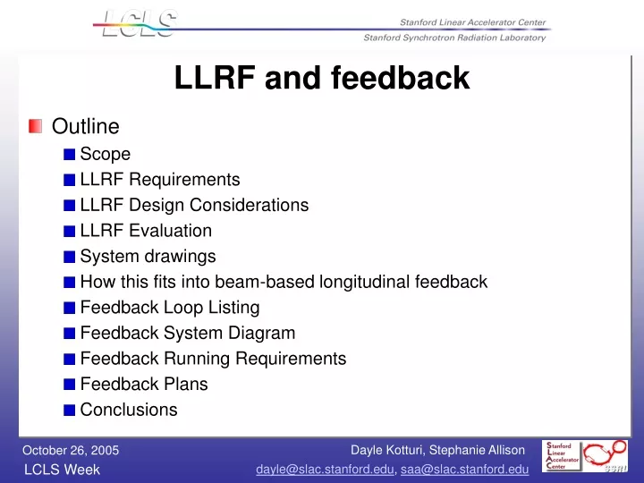
LLRF and feedback • Outline • Scope • LLRF Requirements • LLRF Design Considerations • LLRF Evaluation • System drawings • How this fits into beam-based longitudinal feedback • Feedback Loop Listing • Feedback System Diagram • Feedback Running Requirements • Feedback Plans • Conclusions
Scope (1) • The low level RF controls system consists of RF phase and amplitude controls at these locations: • Laser • Gun (Klystron 20-6) • L0-A, a.k.a. L0-1 (Klystron 20-7) • L0-B, a.k.a. L0-2 (Klystron 20-8) • L0 Transverse cavity (Klystron 20-5) • L1-S (Klystron 21-1) • L1-X (Klystron 21-2) • L2 - (Klystrons 24-1,24-2,24-3) to control avg phase/ampl of L2 • L3 Transverse cavity (Klystron 24-8) • L3 - 2 sectors of klystrons, S29+S30
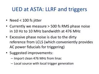
Requirements (1) • At 120 Hz, meet phase/amp noise levels defined as: • 0.1% rms amplitude • 100 fs rms in S-band (fill time = 850 ns) • 125 fs rms in X-band (fill time = 100 ns) • All tolerances are rms levels and the voltage and phase tolerances per klystron for L2 and L3 are Nk larger, assuming uncorrelated errors, where Nk is the number of klystrons per linac (L2 has 28; L3 has 48)
Requirements (2) • When beam is present, control will be done by beam-based longitudinal feedback (except for T-cavs); when beam is absent, control will be done by local phase and amplitude controller (PAC) • Adhere to LCLS Controls Group standards: RTEMS, EPICS, Channel Access protocol • Ref: Why RTEMS? Study of open source real-time OS • Begin RF processing of high-powered structures May, 2006
Design considerations • Through end of January 2005, various solutions were evaluated, from 100% COTS modules to hybrids of in-house designed boards. • By May 2005, the options were narrowed down to two: an Off-the-shelf solution and an in-house solution.
Evaluation (1) • The off-the-shelf solution is: • Expensive ($25K per instance * 10 instances) • Noisy. ADCs are up to 150’ from what they measure so analog noise levels and ground loop problems would need to be dealt with • The in-house solution is: • Possibly longer to develop due to board design and fabrication time
Evaluation (2) • Characteristics of the COTS solution were seen as requiring more effort than those of the in-house solution • Potential offered by the lower cost of the in-house solution to replace 250 klystron controllers in the remainder of the LINAC is attractive • Hardware people were available as of 22aug2005 to work on board design if µcontroller was decided • Turned to the EPICS community for ideas and chose a µcontroller
Evaluation (3) • Lower cost alternatives to the $15K VME chassis and IOC were discussed in the session on hardware at the EPICS Collaboration Meeting. April 27-29, 2005 • Of the options presented, only the Coldfire uCdimm 5282 processor had the communication speed and power to meet our data requirements. Cost is $150 per processor plus the development of the board it sits on
Evaluation (4) • By choosing the Arcturus Coldfire uCdimm 5282 processor, we are able to make use of the port of the operating system, RTEMS, which has already been done. • RTEMS is the standard for the real-time operating system chosen for LCLS by the Controls Group • EPICS, the standard for the control system software for LCLS runs on RTEMS • With these choices, the LLRF control system will be fully integrated into the rest of the LCLS EPICS control system and can speak to other devices and applications such as control panels, alarm handlers and data archivers, using Channel Access protocol, the standard communication protocol for this project.
Feedback Loops* • Beam Energy (120 Hz) • DL1, DL2 • Beam Energy and Bunch Length (120 Hz) • BC1, BC2 • Launch Position and Angle • L1, L2, L3 (10 Hz) • LTU (120 Hz) • Undulator (slow, < 1 Hz) • RF Phase of the Diagnostic Transverse Deflector (120 Hz) • Injector, L3 • Injector Bunch Charge (120 Hz) • Low Frequency Gun Temp Regulation (not in above PRD) (slow) • Injector Laser Steering (see Sheng Peng) • Gun and RF Local Feedback (see Dayle Kotturi) • RF Water Cooling Control (see Stephen Schuh) * see LCLS PRD: Controls Requirements for Feedback Systems by Patrick Krejcik
Fast Feedback in the LCLS Network Xterm SLC Alpha All High Level Apps Xterm Xterm Xterm EPICS Distributed High Level Apps Msgs on PEP Ethernet PEP Proxy SLC Messages over LCLS Ethernet CA over LCLS Ethernet PNet (Pulse ID) MPG EVG P N E T IOC EVR A D C Micro emulator Meas IOCs Micro emulator Actuator IOCs D A C UDP over Private Ethernet Timing Pattern RF ref MPS Beam Position Monitors, Beam Current Toroid, RF Phases Klys Ampls & Phases, Correctors, TCAV RF Phases, Drive Laser Pwr
Feedback Running Requirements (1) • Timing – 8 msec total after beam pulse: • 2 msec: Acquire and process measurements - includes flyer detection, timing pattern check, and beam loss detection. • 1 msec: Transfer data and status from meas IOC(s) to actuator IOC(s) which then compute states and actuator settings using matrix multiplication. Transfer cascade data and status from upstream actuator IOCs to downstream actuator IOCs. • 5 msec: Set actuators and allow settling to within 80-90%. • Also in that 5 msec • Send status of problem actuators to other actuator IOCs in the loop so a bad actuator doesn’t cause runaway. • Average, RMS, chi-square calculations. Update ring buffers. Update status in the database and monitor processing for CA clients. • Save snapshot data if requested. Save ring buffers on beam loss.
Feedback Running Requirements (2) • Cascading of similar feedback loops • Automatic rate changes based on beam • Trajectory loops also work for non-LCLS (i.e. ESA) beam • No CAMAC control or readback required • Calibration (no dither calibration required) • Slow feedback data transfer can be channel access, fast feedback uses dedicated HW • No ramping required (state and actuator setpoints)
Feedback User Interface Requirements • Turn feedback loop on and off • Start/abort/accept calibration • Matrix download (loop off only) • Rate change for slow loops • Change state setpoints • Provide warning and alarm limits on measurements, states, and actuators • Warning and alarm limits on states referenced to setpoints • Warning and alarm limits on measurements referenced to a gold orbit • Set actuators to reference values • Turn on/off specific measurements without stopping feedback loop • Set timing pattern inclusion/exclusion masks • Display of status and ring buffers, get a snapshot on same pulse • Get ring buffers (either current or from a recent beam loss) for offline analysis • Archival of setpoints, readbacks, user input, matrices, ring buffers, etc • Save/restore setpoints, user inputs, matrices.
Feedback Plans for Next Year • Functional requirements and review – Jan 2006 • Use SLC fast feedback as input • Prototype UDP data transfer to check timing – Jan 2006 • Design spec and review – Mar 2006 • Implementation: • Might use same EPICS interface as SLC-aware IOC • Database and subroutines – plan to use record processing for calculations • UDP data transfer driver • Fully operational prototype by Aug 2006
Conclusions • This solution: • corrects the phase and amplitude of the RF at 120 Hz • when there is beam, this system will integrate with the beam-based longitudinal feedback by accepting the latter’s RF phase and amplitude corrections and passing them on • meets the spec for speed and noise • avoids signal noise and ground loop problems • meets LCLS control system requirements and standards running EPICS on RTEMS • provides a low cost path for future upgrade in the rest of the LINAC when the rest of the klystron control is replaced