Download
1 / 18
190 likes | 197 Views
LLRF Controls. Outline Requirements External Interfaces Schedule Date Needed Prototype Completion Date Hardware Order Date Installation Test Period Design Design Maturity (what reviews have been had) State of Wiring Information State of Prototype. Requirements.

E N D
LLRF Controls • Outline • Requirements • External Interfaces • Schedule • Date Needed • Prototype Completion Date • Hardware Order Date • Installation • Test Period • Design • Design Maturity (what reviews have been had) • State of Wiring Information • State of Prototype
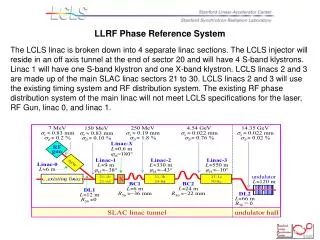
Requirements • At 120 Hz, meet phase/amp noise levels defined as: • 0.1% rms amplitude • 100 fs rms in S-band (fill time = 850 ns) • 125 fs rms in X-band (fill time = 100 ns) • All tolerances are rms levels and the voltage and phase tolerances per klystron for L2 and L3 are Nk larger, assuming uncorrelated errors, where Nk is the number of klystrons per linac (L2 has 28; L3 has 48)
Engineering Requirements • When beam is present, control will be done by beam-based longitudinal feedback (except for T-cavs); when beam is absent, control will be done by local phase and amplitude controller (PAC) • Adhere to LCLS Controls Group standards: RTEMS, EPICS, Channel Access protocol • Ref: Why RTEMS? Study of open source real-time OS • Begin RF processing of high-powered structures May 20, 2006
External Interfaces • LLRF to LCLS global control system • PVs available for edm screens, archiving, etc over controls network • LLRF VME to beam-based longitudinal feedback • from feedback: phase and amplitude corrections at 120 Hz over private ethernet • from LLRF: phase and amplitude values • (internal) LLRF VME to LLRF microcontrollers • from VME: triggers, corrected phase and amplitude • from microcontrollers: phase and amplitude averaged values at 120 Hz, raw phase and amplitude values for debug
Schedule – for PAD • Date Needed: injector: Dec/06 • Prototype Completion Date: • Mar/06: board prototype (2 or 4 chan, thermo) • May/06: final board. Test (incl temp. cycling) • Hardware Order Date: continuous • Hardware Delivery Date: • by Sep/06: chassis (15 dual channel) avail. • Installation: injector: Oct/06 • Test Period: injector: Nov/06
Schedule – for PAC • Date Needed: injector: Dec/06 • Prototype Completion Date: • Jan/06: first board prototype • Mar/06: first board prototype if not same as fast PAC • Hardware Order Date: continuous • Hardware Delivery Date: • by Sep/06: chassis (6 single channel) • Installation: injector: Nov/06 • Test Period: injector: Nov/06
Schedule – for slow PAC • Date Needed: injector: Dec/06 • Prototype Completion Date: • Mar/06: first board prototype if different than fast PAC • Hardware Order Date: continuous • Hardware Delivery Date: • by Sep/06: chassis (6 single channel) • Installation: injector: Nov/06 • Test Period: injector: Nov/06
Schedule – for timing/feedback crate • Date Needed: injector: Dec/06 • Prototype Completion Date: Fall/06 • Hardware Order Date: done • Hardware Delivery Date: have it • Installation: injector: Nov/06 • Test Period: injector: Nov/06
Design • Design maturity (what reviews have been had): • RF/Timing Design, DOE Review, August 11, 2004 • Akre_FAC_Oct04_RF_Timing, FAC Review, October, 2004 • Low Level RF Controls Design, LCLS Week, January 25-27, 2005 • Low Level RF, Lehman Review, May 10-12, 2005 • LLRF Plans for Development and Testing of Controls, LCLS Week, July 21, 2005 • Low Level RF Design, Presentation for Controls Group, Sept. 13, 2005 • LLRF Preliminary Design review, SLAC, September 26, 2005 • LCLS LLRF Control System - Kotturi, LLRF Workshop, CERN, October 10-13, 2005 • LCLS LLRF System - Hong, LLRF Workshop, CERN, October 10-13, 2005 • LLRF and Beam-based Longitudinal Feedback Readiness - Kotturi/Akre, LCLS Week, SLAC, October 24-26, 2005 • LCLS Week LLRF and feedback - Kotturi/Allison, LCLS Week, SLAC, October 24-26, 2005 • LLRF, LCLS System Concept Review/Preliminary Design Review, SLAC, November 16-17, 2005 Comments • LLRF Beam Phase Cavity Preliminary Design review, SLAC, November 30, 2005 Docs at: http://www.slac.stanford.edu/grp/lcls/controls/global/subsystems/llrf • State of wiring: percent complete Captar input will be given at time of presentation • State of prototype: PAD (1 chan ADC) and PAC boards built (shown on next pages).Testing.
Additional Slides • The following two pages show an overview of the LLRF control modules. From these diagrams, counts of module types, as well as function and location are seen.