Download
1 / 26
260 likes | 472 Views
LLRF. Outline System Concept Review Requirements Personnel Engineering requirements Interfaces Alternatives Test plan Preliminary Design Review Block diagram Quality control and reliability Safety hazards. Requirements. At 120 Hz, meet phase/amp noise levels defined as:

E N D
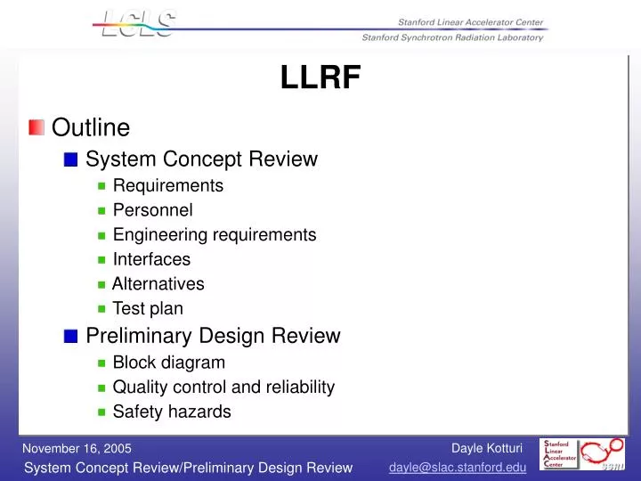
LLRF • Outline • System Concept Review • Requirements • Personnel • Engineering requirements • Interfaces • Alternatives • Test plan • Preliminary Design Review • Block diagram • Quality control and reliability • Safety hazards
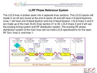
Requirements • At 120 Hz, meet phase/amp noise levels defined as: • 0.1% rms amplitude • 100 fs rms in S-band (fill time = 850 ns) • 125 fs rms in X-band (fill time = 100 ns) • All tolerances are rms levels and the voltage and phase tolerances per klystron for L2 and L3 are Nk larger, assuming uncorrelated errors, where Nk is the number of klystrons per linac (L2 has 28; L3 has 48)
Personnel • Customers = Patrick Krejcik + Paul Emma need LLRF control system thru L1S by Dec 06 • Hardware = Ron Akre, Jeff Olsen, Michael Cecere • Software = Dayle Kotturi, Arturo Alarcon
Engineering Requirements • When beam is present, control will be done by beam-based longitudinal feedback (except for T-cavs); when beam is absent, control will be done by local phase and amplitude controller (PAC) • Adhere to LCLS Controls Group standards: RTEMS, EPICS, Channel Access protocol • Ref: Why RTEMS? Study of open source real-time OS • Begin RF processing of high-powered structures May 20, 2006
Interfaces • LLRF to LCLS global control system • PVs available for edm screens, archiving, etc over controls network • LLRF VME to beam-based longitudinal feedback • from feedback: phase and amplitude corrections at 120 Hz over private ethernet • from LLRF: phase and amplitude values • (internal) LLRF VME to LLRF microcontrollers • from VME: triggers, corrected phase and amplitude • from microcontrollers: phase and amplitude averaged values at 120 Hz, raw phase and amplitude values for debug
Alternatives • Through end of January 2005, various solutions were evaluated, from 100% COTS modules to hybrids of in-house designed boards. • By May 2005, the options were narrowed down to two: an Off-the-shelf solution and an in-house solution. • By August 2005, the in-house solution was selected
Test Plan • Will be described for the 5 categories of hardware • Low level RF chassis (in-house) • Monitor chassis (in-house with COTS timing) • Fast control chassis (in-house with COTS timing) • Slow control chassis (in-house) • Feedback control chassis (COTS products)
Test Plan for Low level RF chassis(in-house) • What for? Low level RF distribution where EPICS is not required • Where? LINAC Sector 0, the RF hut and klystron stations • Status now: 119, 476, 2856, 2830.5 MHz – 16 way distributions complete. 476 MHz master amplifier complete • Steps to complete: • by Nov2005: PEP-II master phase shifter install and test • by Dec2005: IQPAU installation and test • by Jan2006: LO chassis installation and test
Test plan for monitor chassis – “PAD”(in-house with COTS timing) • What for? Local RF phase/amplitude detection/monitoring • Where? Laser, gun, L0-A, L0-B, L1-S • Status now: Evaluating ADCs • Steps to complete: • by Dec2005: evaluation of ADCs (1chan) • by Mar2006: board prototype (2 or 4 chan, thermo) • by May2006: final board. Test (incl temp. cycling) • by Sep2006: chassis (15 dual channel) avail. Test. • by Oct2006: injector installation and test
MONITORS 4 X 16 bit ADC (LTC2208) I&Q MODULATORS FIFO 4 X 1k words 119MHz Clock Line Drivers 16bit DATA 16 bit CONTROL / 3 DATA Chan. 1 I Arcturus RF CHAN 1 WCLK I 1 INPUT uC5282 LO 2 RF Microcontroller Module 16bit DATA ET CS/ Q with 10/100 Ethernet CLK Chan. 1 Q 4 WCLK HERNET 16bit DATA 3 Chan. 2 I RF CHAN 2 WCLK I 1 INPUT LO 2 RF 16bit DATA Chan. 2 Q Q WCLK 4 LO INPUT CPLD EXTERNAL EXTERNAL CLOCK TRIGGER 119MHz 120Hz PAD – the monitor board
Test plan for fast control chassis(in-house with COTS timing) • What for? Local RF phase/amplitude control • Where? Laser, gun, L0-A, L0-B, L1-S • Status now: board design • Steps to complete: • by Jan2006: board prototype • by Mar2006: final board • by Sep2006: chassis (6 single channel) • by end of 2006 downtime: injector install/test
Test plan for slow control chassis (in-house) • What for? Phase and amplitude control of the reference • Where? Sector 20 RF hut • Status now: not started • Steps to complete: • between now and Feb 2006: determine if fast control module does the job. If yes, this is done. Otherwise: • by Feb2006: start design • by Mar2006: board prototype • by May2006: final board • by Sep2006: chassis (6 single channel) • by Nov2006: injector installation and test
RF crate • What for? Local feedback control and timing for RF systems • Where? Sector 20 RF hut • Status now: testing EVR • Steps to complete: • evaluate number of signals and processor load to determine number of crates • design and write software • test with simulation and later hardware • during 2006 downtime: installation and test
Feedback control crate (COTS products) • What for? beam-based longitudinal feedback • Where? At sector 20, in RF hut • Status now: software design • Steps to complete: • purchase network switch module if IOC has insufficient ports • by Dec2006: software • by Dec2006: installation and test
Quality control and reliability • Buy components from reliable vendors • Test each component and circuit board • Components will be tested in an incubator cycled from room temperature through 45 degC
Safety hazards • RF 1kW at 120Hz at 5uS = 0.6 Watts average, 2 Watt average amps at 2856MHz, 60W average amps at 476MHz • Hazards – RF Burns • Mitigation – Avoid contact with center conductor of energized connectors • 110V AC Connector • Require “Electrical Safety 251” completion for plugging/unplugging • Hazards - Shock • Mitigation - Don’t touch conductors when plugging into outlet. • The LLRF system is less hazardous than a cell phone and equally hazardous as plugging in a 110V AC cord at home
Supplementary Slides… • …on next page to end
476 MHz master amplifier PEP-II master phase shifter
LLRF Phase Reference System 2830.5 to 2856MHz Divide by 16 Chassis
LLRF Phase Reference System 119 to 476MHz Divide by 16 Chassis