Download
1 / 27
270 likes | 470 Views
The Gigabit Link Interface Board (GLIB) Paschalis VICHOUDIS CERN PH-ESE-BE. xTCA Interest Group meeting – 07 March 2011. The Team. Sophie Baron Manoel Barros Marin Vincent Bobillier Stefan Haas Magnus Hansen Markus Joos Francois Vasey Paschalis Vichoudis. PH-ESE-BE.

E N D
The Gigabit Link Interface Board (GLIB) Paschalis VICHOUDIS CERN PH-ESE-BE xTCA Interest Group meeting – 07 March 2011
The Team • Sophie Baron • Manoel Barros Marin • Vincent Bobillier • Stefan Haas • Magnus Hansen • Markus Joos • Francois Vasey • Paschalis Vichoudis PH-ESE-BE GLIB project homepage: https://espace.cern.ch/project-GBLIB/public
Outline • INTRODUCTION • IMPLEMENTATION • STATUS & DELIVERABLES
Introduction CONCEPT • THE GLIB IS: an evaluation platform and an easy entry point for users of high speed optical links • THE GLIB IS TARGETED FOR: • optical link evaluation in the laboratory • control, triggering and data acquisition from remote modules in beam or irradiation tests
Introduction OVERVIEW • Mid-size double-width Advanced Mezzanine Card (AMC) • Serves as an evaluation platform and an easy entry point for users of high speed optical links. • 4 SFP+ transceiver modules • Virtex-6 FPGA with twenty 6.5Gbps transceivers. • I/O capability can be further enhanced with two FPGA Mezzanine Cards (FMC). • Gigabit Ethernet link to PC for bench-top operation.
Introduction TYPICAL USE CASES (1/6) BENCH-TOP: beam test setup = SFP+ = TTC FMC
Introduction TYPICAL USE CASES (2/6) BENCH-TOP: front-end module test setup = SFP+ = E-LINK FMC = TTC FMC
Introduction TYPICAL USE CASES (3/6) BENCH-TOP: system test setup = SFP+ = TTC FMC
Introduction TYPICAL USE CASES (4/6) BENCH-TOP: system test setup [remote control/readout] = SFP+ = 10GbE FMC = TTC FMC
Introduction TYPICAL USE CASES (5/6) CRATE: beam test setup = SFP+ = TTC FMC
Introduction TYPICAL USE CASES (6/6) CRATE: system test setup = SFP+ = TTC FMC
Implementation ARCHITECTURE
First Prototype CMS xTCA workshop, 01-Feb-2010
First Prototype CMS xTCA workshop, 01-Feb-2010
Implementation INTERFACES (1/2) Optical • Four SFP+ cages AMC • Port [0-1]: GbE. • Port [4-7] (Fat Pipe): PCIe x4 GEN2. Possibility to implement other protocols. • Port [8-11] (Extended Fat Pipe): PCIe x4 GEN2. Possibility to implement other protocols. • Port [2:3]: LVDS I/O pairs. Possibility to implement other differential I/O standards. • Port [12-15]: LVDS I/O pairs. Possibility to implement other differential I/O standards. • Port [17-20]: M-LVDS. • CLK1/TCLKA: M-LVDS clock input. • CLK2/TCLKB: M-LVDS clock input/output. • CLK3/FCLKA: HCSL/M-LVDS clock input.
Implementation INTERFACES (2/2) FMC • 2 High-pin count (HPC) sockets • 160 user-specific I/Os (single-ended or differential pairs) • 2 differential clock inputs and 2 differential clock outputs. • The primary FMC is accessible from the front panel • The primary FMC also provides four optional 6.5Gbps transceiver lines. PC (only in bench-top operation) • GbE RJ45 socket (1000BASE-T). • PCIe 4x GEN2 adapter board. • Possibility to implement additional PC interfaces on the FMC mezzanines.
Implementation FPGA XILINX Virtex-6 LXT FPGA ( VLX130T, FF1156 package) • 600 I/O that can be configured to various differential or single-ended standards. • 4 Ethernet MAC and 2 PCIe Hard-IP blocks. • 20 6.5Gbps transceivers (MGTs) organized in 5 quads. • ~10Mb of block RAM. • Pin Compatible with higher capacity FPGAs • VLX195, VLX240, VLX365, VSX315
Implementation RAM & MMC On-board memory • Two 72Mb (2M x 36bit) SRAM devices (CY7C1470 by Cypress) • Operating frequency at up to 250MHz. • Upgradeable up to 1.125Gb (once available) Module Management Controller (MMC) • Implements the Intelligent Platform Management Interface (IPMI) for the AMC initialization and monitoring in μTCA environment. • Mezzanine card based on an ATMEL microcontroller. • Developed by CPPM (microcontroller firmware in collaboration with DESY). • Dimensions: 39mm x 20mm x 10mm.
Implementation CLOCK DISTRIBUTION
Implementation MODULE MANAGEMENT CONTROLLER Note: Not required for bench-top applications
Implementation JTAG CIRCUITRY Important for Testing
Implementation POWERING Power budget: Up to 0.5W for Management and 80W for Payload Power
Implementation POSSIBLE FMC IMPLEMENTATIONS
Implementation FIRMWARE ARCHITECTURE
Implementation TESTING • Possibility for boundary scan testing • Use of commercial hardware for creating loopbacks and providing clock I/O for connectivity and clock distribution testing, respectively. • Testing of optical parts (loopbacks w/ optical fibres, BER measurements etc) • Various testpoints on board • Special testing software and firmware
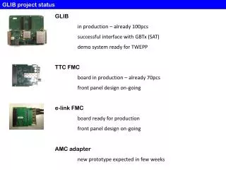
Summary • Specifications:v1.9 available. • Hardware:First prototype available, on-going tests. • Testing tools: Commercial hardware, boundary scan software. • Infrastructure: Crate, MCH available, commercial AMCs available. Getting familiar with. • Software/firmware: Development on-going. Latest news: GLIB has entered the open hardware repository. https://edms.cern.ch/nav/EDA-02180-V1-0 specs from GLIB website GLIB at OHR ** Presented at TWEPP 2010 **
Deliverables The GLIB team envisages to deliver and support software, firmware and hardware for the following 3 setups: • Bench-top beam test setup • Bench-top front-end module test setup • Crate system test setup The required FMCs (TTC & E-Link) will also be delivered and supported. Bench-top beam test setup Bench-top front-end module test setup Crate system test setup = SFP+ = E-LINK FMC = TTC FMC