Download
1 / 26
260 likes | 269 Views
Status of production at LNF. Ch. 43. 3 ch/week. Christmas. E.Dane’ and C. Forti – Meeting with LHCb referees Firenze 14-mar-05. Chamber closing rate (averaged in groups of 3 chambers). Christmas. In last 3 weeks, we closed one chamber every Monday-Wednesday-Friday. Start M1R4.

E N D
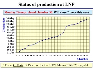
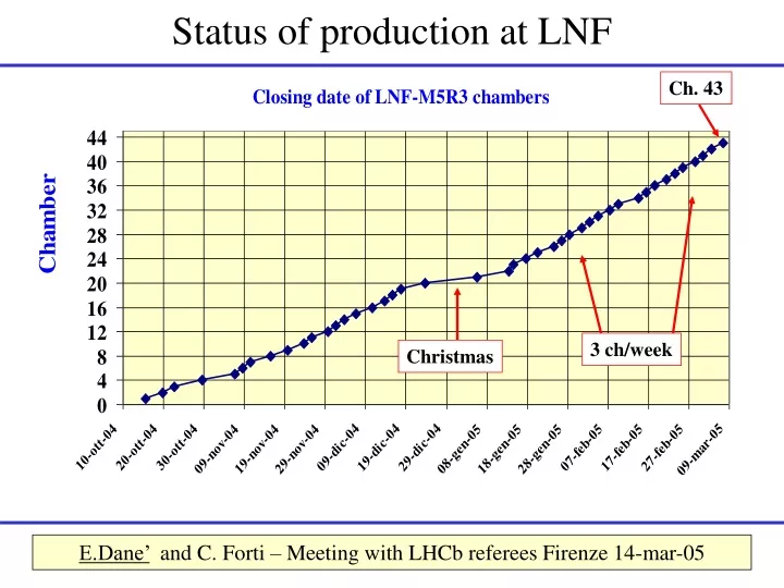
Status of production at LNF Ch. 43 3 ch/week Christmas E.Dane’ and C. Forti – Meeting with LHCb referees Firenze 14-mar-05
Chamber closing rate (averaged in groups of 3 chambers) Christmas In last 3 weeks, we closed one chamber every Monday-Wednesday-Friday
Start M1R4 Start M5R4 today Summer Switch to M1 and Christmas Easter Summer Easter LNF production schedule (updated 8-Mar-05) 56 M3R3 + (52+5) M5R3 + 52 M5R4 + 52 M1R3 + 42 M1R4 = 259 2 weeks (Christmas) + 1w Easter + 4w Summer Switch to M1 ~ 1 month End M5R3=begin-May-05 End M5R4=end-Nov-05 End ALL=mid-sep-06 Assuming a rate of 3 ch./week also for M5:expected end is ~ mid July 2006
LNF-M5R3 gain uniformity (updated 4-march) All 38 tested chambers are GOOD All gaps @ 2.75 kV. No equalization isapplied ±50 V ±80 V
Table for the assembly of two M1 chambers simultaneously GEM group moved to a new clean room and left free space in our clean room. We have equipped this space with a new long table, which will allow to assemble two M1 chambers simultaneously. we firmly believe that we can produce at least 4 M1 chambers per week.
Container for chamber storage and transportation Last Friday we switched on a group of 18 M3R3 chambers (one trolley) using a single HV channel. These chambers have been OFF and flushed with Argon for several months. ~10 days ago we began to flush them with gas mixture 40/40/20. We reached 2.75 kV (in 2 days) without any problem.
Summary of chambers built in Ferrara • Assembled: 49 • Tested 46 • Good (passed the gas leak + HV + source test): 36 • Bad (unrecoverable): 6(CH0,1,3,4,18,27) • To be recovered: 4 (ch 39 for gas leak, ch 2,5,10 for HV) • Chamber #46 has 3 panels recovered from bumps, it passed the HV • test but still needs to be tested with source • At present we have panels ready to assemble 4 more chambers • We have to build 52 (48+spare) chambers • The production status can be checked at the web address: • http://www.lnf.infn.it/esperimenti/lhcb/private/mwpc/construction/php/BuildChamber.php • we are trying to keep it updated on a weekly basis
Ferrara production rate We expect to finish the M2R3 production at the beginning of april
Chambers tests in Ferrara • No big issues with HV training • About 20% have to be recovered (it takes about half a day) • for gas leak • From our preliminary tests all chambers have a very uniform gain: • 95% of each gap area is within 25% wrt the average I @ 2.75kV • Chamber #21 tested in Rome II @ 2850V showed some problems, • it will be tested again • The Rome II source test table is now in Ferrara • Several chambers have been tested in both Ferrara and Rome II • to get normalization constants • In the next weeks the source tests in Ferrara will be normalized • to the standard one
Gas leak and HV test in Ferrara Dark current Gas leak Dark current is measured about 2 hours after reaching 2.85 kV Gas leak is measured @ 5 mbar of overpressure
Status of production at CERN • The change from M3R2 to M2R2 has been carried out without any • major problems. • We are at nominal production speed of 2 chambers per week. • Material supply for M2R1 is already well advanced. • Concerning the panel equipment with electrical components • and the HV-test of panels we are 1 week late. This is due to • increased number of wires to be replacement (problems with tension). The bad winding at the wire spool end causes quite some problem to the wire tension B. Schmidt got in contact with Luma
Chamber production rate @ CERN • We are one week late in regard to our planning. • The delay of the assembly can be recovered more easily. • Strange behavior of leak test for first 2 chambers under investigation Pannelli M2R2 filati Camere M2R2 prodotte
Uniformity of CERN M3R2 chambers • Erica has set up the hardware for the M3R2 uniformity tests. • 8 chambers of this regions have been checked. • We will continue with the tests of this region with the manpower available. • New help from CBPF is foreseen before the next change to M2R1.
Conclusioni di Ferrara • Since beginnning of December we are keeping a constant production rate • of 2 ch/week • The problem of the bumps on the panels (which appeared in January) now • seems to be solved (by drilling holes in the existing panels and improving the • injection technique for the new ones) • The material procurement is OK, apart from minor issues: • In the last batch, 5 panels have problems with the grove for the glue on HV bars • From time to time the wire seems to have some defects • Spool of guard wire twisted • Some difficulties in the HV cables procurement • We still have some difficulties in recovering hospital panels/chambers • (lack of manpower) • We expect to finish the production of M2R3 in about 1 month, for the beginning • of april we need panel of new type (M5R2) • From the next chamber type (M5R2) we plan to implement some small changes • in the tooling to further improve the production
Requirements on MWPC Panel planarity gas gap uniformity: 95% panel area in ± 90 mm (5% in ± 180 mm) PANELS REJECTED ~7% Distance wire plane - cathode plane: PANELS REJECTED: negligible 2.5 mm ± 100 mm Wire pitch: 95% in 2 mm ± 50 mm (5% in 2 mm ± 100 mm) Wire tension: 50 ÷ 90 gWIRES CHANGED < 1‰ Tests on assembled chambers (results shown later for each site) Gas tightness: DP < 2 mbar/hr @ 5 mbar overpressure Partially-tested Small dark current (< 50 nA/chamber) @ 2.85-2.95 kV Fully-tested Gain uniformity: G0/1.7 < G < G0*1.7 (in 100% of each double-gap area) with respect to the average gain G0. The measure of the gas leakage, is obtained by correcting the DP(t) behavior by using the data of the reference chamber.
Gas leakage test (I) In order to minimize the gas refill rate, the maximum leakage allowed for each chamber is 2 mbar/h. To verify the gas tightness of a chamber, we inflate it with nitrogen up to an overpressureDP of 5 mbar. Then, we recordDP as a function of time, during about one hour. The measurement is sensitive to variations of the external temperature. In order to correct this effect, a second chamber is used as a reference. The measure of the gas leakage, is obtained by correcting the DP(t) behavior by using the data of the reference chamber.
Gas leakage test (II) The measure of the gas leakage, is obtained by correcting the DP(t) behavior by using the data of the reference chamber. If a chamber leaks, usually we can recover it by putting glue all around the chamber, between each pair of panels. For ex. In LNF, over 73 chambers produced, only one was not recovered. The measure of the gas leakage, is obtained by correcting the DP(t) behavior by using the data of the reference chamber.
Wire pitch measurement (I) The wire position is precisely determined by the pitch of the wiring machine combs, however it is important to check that no wire is out of the acceptance. The requirement on the wire pitch (WP) is: WP = 2 mm ± 50 µm (95% of pitches) ± 100 µm (5% of pitches) The WP measurement is performed with anautomatic device, based on two cameras scanning the panel and a software for image acquisition and analysis. An accuracy of about 20 µm is obtained. Sample image from scanning device The measure of the gas leakage, is obtained by correcting the DP(t) behavior by using the data of the reference chamber.
Wire pitch measurement (II) The range 2 mm±50 µm corresponds to the red lines drawn at 211 ± 5 pixels. For example in LNF, over all chambers produced (~180,000 wires), we changed only few wires with wrong pitch. The fraction is somewhat higher at CERN, where the wires touch the HV bars, but this is not a cause of worry. The measure of the gas leakage, is obtained by correcting the DP(t) behavior by using the data of the reference chamber.
Photodiode Laser Mechanical excitation wire Panel Wire Tension Measurement in FE This method has been developed together with Firenze and Roma II The signal is sent to a PC’s soundcard, a FFT is applied and the fundamental frequency is searched between 310 and 600 Hz (for M2R3 panels)
Photodiode Laser Mechanical Excitation Wire Tension Measurement in FE The measurement takes about 2 sec/wire (2 panels ~1200 wires in 40 min)
X position in the gap (Wire-pad #) Measurement of the gain uniformity Uniformity of the gapgain is measured with a radioactive source. The current drawn by each gap is monitored while the lead case containing the source is moved by means of a mechanical arm. These measurements allow to check the gain uniformity within each gap and to compare different chambers among them. The method used is similar in INFN and PNPI sites. At CERN, where chambers are smaller, a different method is used (see later). Example of a result of the scan of a gap with radioactive source Y position in the gap Current (nA) The measure of the gas leakage, is obtained by correcting the DP(t) behavior by using the data of the reference chamber.
241Am source Test of CERN chambers with radioactive source: method • All anodes connected together ADC Amplitude spectrum • Cathode connected to the delay line TDC Pad location ADC spectrum Delay line output Peak position of the signal induced by the gammas of the 241Am Time (ns)
Classification criteria on gain average and uniformity Testbeam oct. ’03: 2-GAP The HV plateau width is determined by the minimum efficiency and by the maximum average number of pad-hit. From test-beams, these requirements define a ~170 V wide regionDV = ±85 V For each double-gap, we provide the class: A = all currents measured with source are within a factor 1.4 from the average currentof all 2-gaps ( DV = ±50 V) B = … within a factor 1.7( DV = ±80 V) C = not satisfying criteria A and B Chamber class: AA,AB,BA GOOD BB RESERVE BC,CB,CC REJECTED