Download
1 / 20
230 likes | 313 Views
UART Protocol Chapter 11. Sepehr Naimi. www.NicerLand.com. Topics. Communication theory Parallel vs. Serial Direction: Simplex, Half duplex, Full duplex Synchronization: Synchronous vs. Asynchronous Line coding UART protocol UART in AVR UART Registers Some programs.

E N D
UART ProtocolChapter 11 Sepehr Naimi www.NicerLand.com
Topics • Communication theory • Parallel vs. Serial • Direction: Simplex, Half duplex, Full duplex • Synchronization: Synchronous vs. Asynchronous • Line coding • UART protocol • UART in AVR • UART Registers • Some programs
Parallel vs. Serial • Parallel • For short distances • Not applicable for long distances • More expensive • Cross-talk problem
Direction • Simplex • Half Duplex • Full Duplex
Synchronization • Synchronous • Asynchronous
Line coding TTL NRZ-I RS232 • Line coding: presenting data using signals • Digital • NRZ-L: Coding using level of voltage • TTL • RS232 • NRZ-I: Inverting or not inverting • Analog: using sine waves • ASK • FSK • PSK
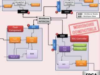
UART Protocol • Serial • Asynchronous • Full duplex
USART (Universal Synchronous Asynchronous Receive Transmit) • USART devices can be used to communicate asynchronously (UART) and synchronously. • Since the synchronous capability of USART is not used nowadays, we concentrate on UART.
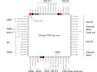
UART in AVR • Control registers: (initialize speed, data size, parity, etc) • UBRR, UCSRA, UCSRB, and UCSRC • Send/receive register • UDR • Status register • UCSRA
Baud rate System clock UART baud rate
Example: Find the UBRR value for 9600bps. • Solution:
UCSRB • RXCIE0 (Bit 7): Receive Complete Interrupt Enable • To enable the interrupt on the RXC0 flag in UCSR0A you should set this bit to one. • TXCIE0 (Bit 6): Transmit Complete Interrupt Enable • To enable the interrupt on the TXC0 flag in UCSR0A you should set this bit to one. • UDRIE0 (Bit 5): USART Data Register Empty Interrupt Enable • To enable the interrupt on the UDRE0 flag in UCSR0A you should set this bit to one. • RXEN0 (Bit 4): Receive Enable • To enable the USART receiver you should set this bit to one. • TXEN0 (Bit 3): Transmit Enable • To enable the USART transmitter you should set this bit to one. • UCSZ02 (Bit 2): Character Size • This bit combined with the UCSZ1:0 bits in UCSRC sets the number of data bits (character size) in a frame. • RXB80 (Bit 1): Receive data bit 8 • This is the ninth data bit of the received character when using serial frames with nine data bits. • TXB80 (Bit 0): Transmit data bit 8 • This is the ninth data bit of the transmitted character when using serial frames with nine data bits.
UCSRC • UMSEL01:00 (Bits 7:6): USART Mode Select • These bits select the operation mode of the USART: • 00 = Asynchronous USART operation • 01 = Synchronous USART operation • 10 = Reserved • 11 = Master SPI (MSPIM) • UPM01:00 (Bit 5:4): Parity Mode • These bits disable or enable and set the type of parity generation and check. • 00 = Disabled • 01 = Reserved • 10 = Even Parity • 11 = Odd Parity • USBS0 (Bit 3): Stop Bit Select • This bit selects the number of stop bits to be transmitted. • 0 = 1 bit • 1 = 2 bits • UCSZ01:00 (Bit 2:1): Character Size • These bits combined with the UCSZ02 bit in UCSR0B set the character size in a frame. • UCPOL0 (Bit 0): Clock Polarity • This bit is used for synchronous mode.
UCSRA • RXC0 (Bit 7): USART Receive Complete 0 • This flag bit is set when there are new data in the receive buffer that are not read yet. It is cleared when the receive buffer is empty. It also can be used to generate a receive complete interrupt. • TXC0 (Bit 6): USART Transmit Complete 0 • This flag bit is set when the entire frame in the transmit shift register has been transmitted and there are no new data available in the transmit data buffer register (TXB). It can be cleared by writing a one to its bit location. Also it is automatically cleared when a transmit complete interrupt is executed. It can be used to generate a transmit complete interrupt. • UDRE0 (Bit 5): USART Data Register Empty 0 • This flag is set when the transmit data buffer is empty and it is ready to receive new data. If this bit is cleared you should not write to UDR0 because it overrides your last data. The UDRE0 flag can generate a data register empty interrupt. • FE0 (Bit 4): Frame Error 0 • This bit is set if a frame error has occurred in receiving the next character in the receive buffer. A frame error is detected when the first stop bit of the next character in the receive buffer is zero. • DOR0 (Bit 3): Data OverRun 0 • This bit is set if a data overrun is detected. A data overrun occurs when the receive data buffer and receive shift register are full, and a new start bit is detected. • PE0 (Bit 2): Parity Error 0 • This bit is set if parity checking was enabled (UPM1 = 1) and the next character in the receive buffer had a parity error when received. • U2X0 (Bit 1): Double the USART Transmission Speed 0 • MPCM0 (Bit 0): Multi-processor Communication Mode 0
Program: sending character ‘G’ continuously #include <avr/io.h> voidusart_init(void) { UCSR0B = (1<<TXEN0); UCSR0C = (1<<UCSZ01)|(1<<UCSZ00); UBRR0L = 103;//baud rate = 9600bps } voidusart_send(unsignedcharch) { while(! (UCSR0A& (1<<UDRE0)));//wait until UDR0 is empty UDR0=ch;//transmit ch } intmain(void) { usart_init(); //initialize the USART while(1) //do forever usart_send('G'); //transmit ‘G’ letter return 0; }
Program 2: It receives bytes of data serially and puts them on Port B. #include <avr/io.h> intmain(void) { DDRB=0xFF;//Port B is output UCSR0B= (1<<RXEN0); //initialize USART0 UCSR0C= (1<<UCSZ01)|(1<<UCSZ00); UBRR0L=103; while(1) { while(!(UCSR0A&(1<<RXC0)));//wait until new data PORTB=UDR0; } return0; }