Download
1 / 34
530 likes | 1.21k Views
UART. ELEC 418 Advanced Digital Systems Dr. Ron Hayne Images Courtesy of Thomson Engineering. UART. Universal Asynchronous Receiver Transmitter Serial Data Transmission. 68HC11 Microcontroller. UART Registers RSR Receive Shift Register RDR Receive Data Register

E N D
UART ELEC 418 Advanced Digital Systems Dr. Ron Hayne Images Courtesy of Thomson Engineering
UART • Universal Asynchronous Receiver Transmitter • Serial Data Transmission 418_11
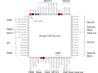
68HC11 Microcontroller • UART Registers • RSR Receive Shift Register • RDR Receive Data Register • TDR Transmit Data Register • TSR Transmit Shift Register • SCCR Serial Communications Control Register • SCSR Serial Communications Status Register • UART Flags • TDRE Transmit Data Register Empty • RDRF Receive Data Register Full 418_11
UART Block Diagram 418_11
Transmitter Operation • Microcontroller waits until TDRE = '1' • Loads data into TDR • Clears TDRE • UART transfers data from TDR to TSR • Sets TDRE • UART outputs start bit ('0') then shifts TSR right eight times followed by a stop bit ('1') 418_11
Transmitter SM Chart 418_11
Transmitter VHDL Model library IEEE; use IEEE.std_logic_1164.all; use IEEE.numeric_std.all; entity UART_Transmitter is port(Bclk, sysclk, rst_b, TDRE, loadTDR: in std_logic; DBUS: in unsigned(7 downto 0); setTDRE, TxD: out std_logic); end UART_Transmitter; 418_11
Transmitter VHDL Model architecture xmit of UART_Transmitter is type stateType is (IDLE, SYNCH, TDATA); signal state, nextstate: stateType; signal TSR: unsigned(8 downto 0); signal TDR: unsigned(7 downto 0); signal Bct: integer range 0 to 9; signal inc, clr, loadTSR, shftTSR, start: std_logic; signal Bclk_rising, Bclk_Dlayed: std_logic; begin TxD <= TSR(0); setTDRE <= loadTSR; Bclk_rising <= Bclk and (not Bclk_Dlayed); 418_11
Transmitter VHDL Model Xmit_Control: process(state, TDRE, Bct, Bclk_rising) begin inc <= '0'; clr <= '0'; loadTSR <= '0'; shftTSR <= '0'; start <= '0'; case state is when IDLE => if (TDRE = '0') then loadTSR <= '1'; nextstate <= SYNCH; else nextstate <= IDLE; end if; 418_11
Transmitter VHDL Model when SYNCH => if (Bclk_rising = '1') then start <= '1'; nextstate <= TDATA; else nextstate <= SYNCH; end if; when TDATA => if (Bclk_rising = '0') then nextstate <= TDATA; elsif (Bct /= 9) then shftTSR <= '1'; inc <= '1'; nextstate <= TDATA; else clr <= '1'; nextstate <= IDLE; end if; end case; end process; 418_11
Transmitter VHDL Model Xmit_update: process(sysclk, rst_b) begin if (rst_b = '0') then TSR <= "111111111"; state <= IDLE; Bct <= 0; Bclk_Dlayed <= '0'; elsif (sysclk'event and sysclk = '1') then state <= nextstate; if (clr = '1') then Bct <= 0; elsif (inc = '1') then Bct <= Bct + 1; end if; 418_11
Transmitter VHDL Model if (loadTDR = '1') then TDR <= DBUS; end if; if (loadTSR = '1') then TSR <= TDR & '1'; end if; if (start = '1') then TSR(0) <= '0'; end if; if (shftTSR = '1') then TSR <= '1' & TSR(8 downto 1); end if; Bclk_Dlayed <= Bclk; end if; end process; end xmit; 418_11
Receiver Operation • UART waits for start bit • Shifts bits into RSR • When all data bits and stop bit are received • RSR loaded into RDR • Set RDRF • Microcontroller waits until RDRF is set • Read RDR • Clear RDRF 418_11
Sampling RxD 418_11
Receiver SM Chart 418_11
Receiver VHDL Model library IEEE; use IEEE.std_logic_1164.all; use IEEE.numeric_std.all; entity UART_Receiver is port(RxD, BclkX8, sysclk, rst_b, RDRF: in std_logic; RDR: out unsigned(7 downto 0); setRDRF, setOE, setFE: out std_logic); end UART_Receiver; 418_11
Receiver VHDL Model architecture rcvr of UART_Receiver is type stateType is (IDLE, START_DETECTED, RECV_DATA); signal state, nextstate: stateType; signal RSR: unsigned(7 downto 0); signal ct1 : integer range 0 to 7; signal ct2 : integer range 0 to 8; signal inc1, inc2, clr1, clr2, shftRSR, loadRDR: std_logic; signal BclkX8_Dlayed, BclkX8_rising: std_logic; begin BclkX8_rising <= BclkX8 and (not BclkX8_Dlayed); 418_11
Receiver VHDL Model Rcvr_Control: process(state, RxD, RDRF, ct1, ct2, BclkX8_rising) begin inc1 <= '0'; inc2 <= '0'; clr1 <= '0'; clr2 <= '0'; shftRSR <= '0'; loadRDR <= '0'; setRDRF <= '0'; setOE <= '0'; setFE <= '0'; case state is when IDLE => if (RxD = '0') then nextstate <= START_DETECTED; else nextstate <= IDLE; end if; 418_11
Baud Rate Generator 418_11
VHDL Model entity clk_divider is port(Sysclk, rst_b: in std_logic; Sel: in unsigned(2 downto 0); BclkX8: buffer std_logic; Bclk: out std_logic); end clk_divider; architecture baudgen of clk_divider is signal ctr1: unsigned(3 downto 0) := "0000"; -- divide by 13 counter signal ctr2: unsigned(7 downto 0) := "00000000"; -- div by 256 ctr signal ctr3: unsigned(2 downto 0) := "000"; -- divide by 8 counter signal Clkdiv13: std_logic; 418_11
VHDL Model begin process(Sysclk) -- first divide system clock by 13 begin if (Sysclk'event and Sysclk = '1') then if (ctr1 = "1100") then ctr1 <= "0000"; else ctr1 <= ctr1 + 1; end if; end if; end process; Clkdiv13 <= ctr1(3); 418_11
VHDL Model process(Clkdiv13) -- ctr2 is an 8-bit counter begin if (Clkdiv13'event and Clkdiv13 = '1') then ctr2 <= ctr2 + 1; end if; end process; BclkX8 <= ctr2(to_integer(sel)); -- MUX process(BclkX8) begin if (BclkX8'event and BclkX8 = '1') then ctr3 <= ctr3 + 1; end if; end process; Bclk <= ctr3(2); end baudgen; 418_11
Complete UART entity UART is port(SCI_sel, R_W, clk, rst_b, RxD: in std_logic; ADDR2: in unsigned(1 downto 0); DBUS: inout unsigned(7 downto 0); SCI_IRQ, TxD, RDRF_out, Bclk_out, TDRE_out: out std_logic); end UART; architecture uart1 of UART is component UART_Receiver port(RxD, BclkX8, sysclk, rst_b, RDRF: in std_logic; RDR: out unsigned(7 downto 0); setRDRF, setOE, setFE: out std_logic); end component; 418_11
Complete UART component UART_Transmitter port(Bclk, sysclk, rst_b, TDRE, loadTDR: in std_logic; DBUS: in unsigned(7 downto 0); setTDRE, TxD: out std_logic); end component; component clk_divider port(Sysclk, rst_b: in std_logic; Sel: in unsigned(2 downto 0); BclkX8: buffer std_logic; Bclk: out std_logic); end component; 418_11
Complete UART signal RDR, SCSR, SCCR: unsigned(7 downto 0); signal TDRE, RDRF, OE, FE, TIE, RIE: std_logic; signal BaudSel: unsigned(2 downto 0); signal setTDRE, setRDRF, setOE, setFE, loadTDR, loadSCCR: std_logic; signal clrRDRF, Bclk, BclkX8, SCI_Read, SCI_Write: std_logic; begin RCVR: UART_Receiver port map(RxD, BclkX8, clk, rst_b, RDRF, RDR, setRDRF, setOE, setFE); XMIT: UART_Transmitter port map(Bclk, clk, rst_b, TDRE, loadTDR,DBUS, setTDRE, TxD); CLKDIV: clk_divider port map(clk, rst_b, BaudSel, BclkX8, Bclk); 418_11
Microcontroller Interface • Memory-Mapped I/O 418_11
UART Test Bench entity UART_test is end UART_test; architecture test1 of UART_test is component UART port(SCI_sel, R_W, clk, rst_b, RxD: in std_logic; ADDR2: in unsigned(1 downto 0); DBUS: inout unsigned(7 downto 0); SCI_IRQ, TxD, RDRF_out, Bclk_out, TDRE_out: out std_logic); end component; signal SCI_sel, R_W, clk, rst_b, RxD, SCI_IRQ, TxD, RDRF, Bclk, TDRE: std_logic := '0'; signal ADDR2: unsigned(1 downto 0); signal DBUS: unsigned(7 downto 0); 418_11
UART Test Bench begin uart1: UART port map (SCI_sel, R_W, clk, rst_b, RxD, ADDR2, DBUS, SCI_IRQ, TxD, RDRF, Bclk, TDRE); clk <= not clk after 50 ns; process begin wait for 120 ns; rst_b <= '1'; SCI_sel <= '1'; DBUS <= "10000000"; ADDR2 <= "10"; R_W <= '1'; wait for 100 ns; 418_11
DBUS <= "01101001"; ADDR2 <= "00"; wait for 100 ns; R_W <= '0'; wait until TDRE = '1'; DBUS <= "00111100"; R_W <= '1'; wait for 100 ns; R_W <= '0'; wait until TDRE = '1'; DBUS <= "10101010"; R_W <= '1'; wait for 100 ns; R_W <= '0'; wait; end process; end test1; UART Test Bench 418_11
ModelSim Simulation 418_11
ModelSim Simulation 418_11
RxD <= TxD; process begin wait for 120 ns; report "Begin Testing"; rst_b <= '1'; SCI_sel <= '1'; -- Set SCCR DBUS <= "10000000"; ADDR2 <= "10"; R_W <= '1'; wait for 100 ns; -- Load TDR DBUS <= "01101001"; ADDR2 <= "00"; wait for 100 ns; DBUS <= "ZZZZZZZZ"; R_W <= '0'; wait until RDRF = '1'; assert DBUS = "01101001" report "Test Failed"; report "Testing Complete"; wait; Loop-Back Test 418_11
Loop-Back Test 418_11
Summary • Universal Asynchronous Receiver Transmitter • Transmitter • Receiver • Baud Rate Generator • VHDL Models • ModelSim Simulation 418_11