Download
1 / 29
290 likes | 629 Views
Model for Ullage Flammability, Ignition and Explosion – BlazeTank. by N. Albert Moussa and Venkat Devarakonda BlazeTech 24, Throndike St, Cambridge, MA 02141 (617) 661 0700 Fax. (617) 661 9242 www.blazetech.com and Gregory Czarnecki US Air Force, 46th Test Wing, WPAFB, OH 45433-7605

E N D
Model for Ullage Flammability, Ignition and Explosion – BlazeTank by N. Albert Moussa and Venkat Devarakonda BlazeTech 24, Throndike St, Cambridge, MA 02141 (617) 661 0700 Fax. (617) 661 9242 www.blazetech.com and Gregory Czarnecki US Air Force, 46th Test Wing, WPAFB, OH 45433-7605 Presented at The Fourth Triennial International Fire and Cabin Safety Research Conference, Sponsored by the FAA and CAA 15 – 18 November, 2004 Lisbon, Portugal
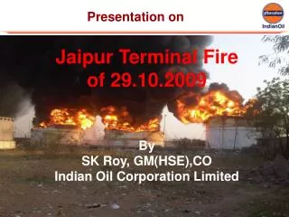
Background • Recent accidents involving center wing fuel tank explosions • May 1990, Philippine Airlines 737, 8 fatalities • July 17, 1996 TWA 747, 230 fatalities • March 3, 2001, Thai Airlines 737-300, 1 fatality • Consequent concern about ullage tank flammability and explosion
When is Ullage Flammable? • Ullage is flammable (ARAC) during: • 30% of the operational time for heated CWT • 4 to 6% of operational time for unheated CWT • 2 to 4% of operational time for main wing tanks • Factors governing flammability include: • Fuel properties, temperature and tank design • Flight mission profile • Environmental conditions • External factors: heat rejection from surrounding equipment
BlazeTank* Model Capabilities • Engineering model developed by BlazeTech over the last 10 years for commercial and military aircraft • Model is general and can be run for any fuel • Key modules of BlazeTank • Ullage flammability • Ignition • Deflagration • Moussa, N.A. et al, “BlazeTank Model for the Flammability, Ignition and Overpressure in an Aircraft Fuel Tank,” presented at the FAA’s Conf. on Aircraft Fire and Cabin Safety Research, Atlantic City, NJ., Nov. 1998. • Also, supported in part by Contract F08635-02-C-0167
Model Inputs Output Temp. and concentration vs. Fuel Conditions: type, amount & height and time temperature Flammable volume inside fuel Tank Geometry and dimensions tank BlazeTank Ignition Characterization: Source Ignition and Propagation location, type and strength If explosion occurs, Temp., burn Flight Profile: Altitude versus time, rate and Overpressure vs. time Fuel extraction rate to engine, and Fuel and tank wall temperatures Overall Model Architecture
1. Ullage Flammability • BlazeTankTM predicts the ullage flammability accounting for the following effects • Flow in and out of the vent • Stratification • Solubility of oxygen and nitrogen • Oxygen evolution during scrub, wash and refueling • Droplets suspended in ullage due to tank slosh and vibration (enhanced evaporation induced by the ignition source can create a localized flammable zone in an otherwise fuel lean ullage)
Two Solutions • Well Mixed Tank • Concentration gradients in fuel tank (1 D) • Near fuel surface, vapor concentration corresponds to saturated vapor pressure • Near a vent, vapor concentration is lower
Model Predictions vs. Test Data • Test data selected for comparison (Sagebiel, J.C., 1997): • Flight tests to emulate TWA 800 • 3 flights conducted successively • 50 gallons of Jet A from Athens was added to CWT • Ullage vapors collected in vacuum containers and analyzed for hydrocarbons • BlazeTank • Used the upper and the lower limits on measured fuel temperatures before takeoff • Used the fuel vapor pressure data from Shepherd et al (2000)
Ullage Flammability: BlazeTank Predictions vs. Test Data Flammable Not Flammable
2. Ignition • BlazeTankTM includes models for the following main modes of ignition • Ignition source • spark • high speed fragment • hot surface ignition • .........
T (t) x b Temperature Hot Spot, T Reaction Rate w Hot Surface Ignition • Minimum Ignition Temperature occurs when heat loss rate at tank wall • = heat release rate due to combustion (Vant Hoff criterion)
Ignition Kinetics Source: Mullins, B.P., Fuel, London, 23, pp. 234-252, 1953.
Hot Surface Ignition Temperature (HSIT) for Jet A Vapors • 9 ft3 fuel tank • Tank pressure = 1 atm • Time for ignition = 10 – 60 s • Trends consistent with Kuchta et al (1965): HSIT decreases with increasing hot surface area
3. Deflagration Analysis Ignition and flame propagation in premixed fuel vapor and air
Deflagration Model • Key assumptions • Ullage consists of two zones: burned and unburned gases • Unburned gases are pressurized by expanding burnt zone • Burning velocity = f(fuel type, stoichiometry, T and P) from literature • Pressure in ullage remains spatially uniform. It equilibrates at acoustic speed >> deflagration speed • BlazeTank solves for the following coupled equations • Continuity • Energy • Species mass conservation
Fuel Properties Required for Deflagration Calculations • Molecular formula and molecular weight • Density • Vapor pressure (Antoine coefficients) • Flammability limits • Heat of formation or heat of combustion • Heat capacity as a function of temperature • Burning velocity parameters
Verification and Validation of Deflagration Model • We compared BlazeTankTM model against test data generated during the TWA 800 accident investigation • Available data sets: • 2 data sets from single compartment tests in ARA’s Quarter scale CWT • 3 data sets from tests in JPL’s HYJET test facility
Quarter Scale Test Facility Depth of the test chamber = 255”
HYJET Test Facility • Ignition Source: H2/O2 combustion in driver creates a torch that breaks a diaphragm and enters the receiver tank • Receiver Tank Volume = 1.180 m3 • Driver Tank Volume = 0.028 m3
Sample BlazeTank OutputUnburned Gas Temperature Tunburned increases by a maximum of a few hundred degrees due to compression by burnt gases: consistent with Metghalchi and Keck (1982)
Sample BlazeTank OutputBurned Gas Temperature • Temperature of burned gases • initially = AFT at constant pressure • decreases rapidly initially due to large flame specific area • increases later as specific area decreases • Maximum temp. of burned gases << AFT at constant volume
Comparison of BlazeTank Predictions with Tests in Quarter Scale CWT for TWA 800 J. E. Shepherd et al, “Results of 1/4-scale experiments, vapor simulant and liquid Jet A tests” Explosion Dynamics Laboratory Report FM 98-6, July 1998
Comparison of BlazeTank Predictions with Tests in Cylindrical Hyjet Tank J. E. Shepherd et al, “Results of 1/4-scale experiments, vapor simulant and liquid Jet A tests” Explosion Dynamics Laboratory Report FM98-6, July 1998
Conclusions • BlazeTankTM accounts for most of the key processes associated with fuel tank ullage explosion • Ullage flammability including transient effects • Various types of ignition sources • Explosion overpressures, flame temperatures and burn velocities • Parametric calculations over a wide range of conditions yield reasonable predictions verifying the model • Model predictions agree very well with test measurements validating the model
Applications of BlazeTank • Aircraft related • Investigation of accidents related to fuel tank flammability • Evaluation of various fuel tank protection technologies e.g., deviations from 12% O2 requirement in fuel tanks due to • improper mixing • OBIGGS equipment malfunction • Assessment of the effect of variations in fuel properties • Fuel tank vulnerability to terrorist attacks • Assessment of deflagration hazards in closed/vented tanks containing flammable liquids/vapors • Tanks in automobiles, trucks, tankers, ships, barges, etc. • Industrial storage tanks • Storage bottles in laboratories