Download
1 / 51
540 likes | 570 Views
Lathe and drilling machines. Unit V. Manufacturing process. It is a process which involves the conversion of raw materials into desired product. Methods involved. Material removal Assembly or joining process Finishing process. Material removal operation.

E N D
Lathe and drilling machines Unit V
Manufacturing process • It is a process which involves the conversion of raw materials into desired product.
Methods involved • Material removal • Assembly or joining process • Finishing process
Material removal operation • It involves removal of extra material from the given material to obtain required dimension of product. • Material removal can be in small scale or large scale small scale – fitting, craftwork etc large scale – industrial products.
Tool • A tool is a device use to carry out various manufacturing operation. • Hand tools. • Machine tools
Hand tools • Tools which are used manually by human effort. • Files • hacksaw
Machine tools • Defined as power driven machine which accomplishes the cutting operation or machining operations.
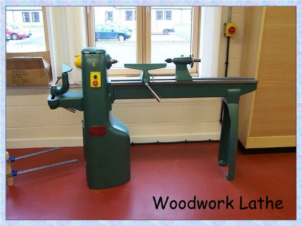
Lathe • A lathe is machine tool employed generally to produce circular objects. • Operations • Drilling • Grinding • Shaping • Milling
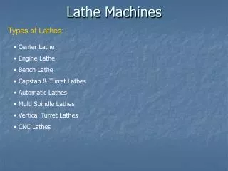
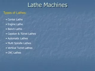
Classification of lathe • Engine lathe • Speed lathe • Turret lathe • Capstan lathe • Automatic lathe • Computer numerically controlled lathe.
Lathe principle of working • A lathe works on the principle that “a cutting tool can remove chips from the rotating work pieces to produce circular objects”.
Figure shows a work holding device known as chuck and is rotated a very high speed. • A V-shaped cutting tool is held against the work piece. • When the tool is moved parallel to axis of work piece material is removed.
Major components • Bed • Head stock • Tail stock • Carriage assembly • Main drive
Bed • It is the foundation part of lathe and supports all its parts. • Top of bed has a guide way which is machined to precision. • Head stock • Main spindle projects out from headstock. • Housing comprises of feed gear box and cone pulley. • Rigidly mounted on bed.
Tail stock • Movable part of the lathe that carries dead centre. • Main function is to support the free end of the work piece. • Also used to clamp tools like twist drill and reamers for making holes. • Tailstock is mounted loosely on guide ways can be moved and locked in position.
Carriage assembly • Saddle • Cross slide • Compound rest • Apron • Tool post
Saddle • H shaped casting that slides over the outer set of guide ways • Serves as base for cross slide. • Cross slide • It is mounted on the saddle. • Enables lateral movement of cutting tool laterally by means of cross slide handwheel.
Compound rest • Mounted on top of cross slide and supports the tool post. • It can be swiveled at an angle to perform taper turning operation. • Tool post • It is used to clamp the tool holder in position.
Apron • It is the part which is fitted saddle, facing operator. • It houses levers, hand wheels mechanism for manual and automatic movement of carriage assembly.
Main drive • It is an electric motor which drives the spindle through transmission system.
Other component • Lead screw • It is a rod which runs longitudinally in front of lathe bed. • The rotation of lead screw moves the carriage to and fro longitudinally during thread cutting operation.
Lathe specifications • Maximum diameter of the workpiece that can be revolved over the lathe bed. • Maximum diameter and width of the workpiece that can revolve over gap in bed.
Maximum length of workpiece that can be mounted between centers. • Overall length of the bed.
Lathe operations • Turning • Taper turning • Facing • Thread cutting • Knurling
Turning • It is an operation in which the workpiece is reduced to the cylindrical section of required diameter.
Operation is carried out with a single point cutting tool. • Work piece is supported between the two centers permit rotation of workpiece.
Tool is fed perpendicular to the axis of workpiece to a known depth and then moved parallel to axis of work.
Facing • An operation performed on lathe to generate flat surface. • Direction of feed is perpendicular to the axis of the lathe.
Length of the work should not be extended more than 1.5 times the diameter of the work piece.
Knurling • Operation performed on lathe to generate serrated surface. • Tool used is called as “knurling tool”.
Tool consist of one upper roller and one lower roller which contains the impression. • Tool is set in such a way that both rollers touch the work.
Low speed of about 60 to 80 rpm and feed is 0.38 to 0.78mm/revolution.
Taper Turning • It is the operation of reducing the diameter of the workpiece gradually along its length. Different types of Taper turning • Compound slide swivelling method • Tailstock offset
Axis of the tool is moved inclined to produce the required taper. • Compound rest which supports tool post is swiveledat required taper angle and locked.
In this method the workpiece is inclined with respect to the lathe axis. • Tool movement is in line with the lathe axis to produce taper. • Tail stock is shifted by a small distance called offset.
Thread cutting • A thread is a helical shaped groove formed on cylindrical surface of workpiece. • Thread cutting is an operation performed on lathe to produce threads by using a tool whose shape will be same as that of thread.
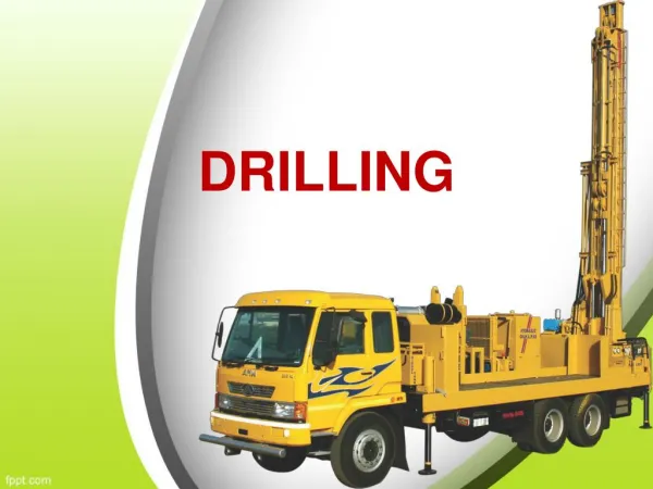
Drilling • Drilling is an operation to produce a cylindrical hole in workpiece. • Tool used is called as “drill bit”. • Tool is held on the tailstock and stationary. • Work is held in chuck. • Tool is fed against the revolving work by rotating hand wheel.