Download
1 / 27
270 likes | 519 Views
Phasor Diagrams and Impedance. Set Phasors on Stun. 1. Sinusoids-amplitude, frequency and phase (Section 8.1) 2. Phasors-amplitude and phase (Section 8.3 [sort of]) 2a. Complex numbers (Appendix B). Set Phasors on Kill. 3. Complex exponentials-amplitude and phase

E N D
Phasor Diagrams and Impedance Lecture 21
Set Phasors on Stun 1. Sinusoids-amplitude, frequency and phase (Section 8.1) 2. Phasors-amplitude and phase (Section 8.3 [sort of]) 2a. Complex numbers (Appendix B). Lecture 21
Set Phasors on Kill 3. Complex exponentials-amplitude and phase 4. Relationship between phasors, complex exponentials, and sinusoids 5. Phasor relationships for circuit elements (Section 8.4) 5a. Arithmetic with complex numbers (Appendix B). Lecture 21
Set Phasors on Vaporize 6. Fundamentals of impedance and admittance (some of Section 8.5) 7. Phasor diagrams (some of Section 8.6) Lecture 21
Phasor Diagrams • A phasor diagram is just a graph of several phasors on the complex plane (using real and imaginary axes). • A phasor diagram helps to visualize the relationships between currents and voltages. Lecture 21
An Example 2mA 40 + + VC 1mF - V + 1kW VR - - Lecture 21
An Example (cont.) I = 2mA 40 VR = 2V 40 VC = 5.31V -50 V = 5.67V -29.37 Lecture 21
Phasor Diagram Imaginary Axis Real Axis V VC VR Lecture 21
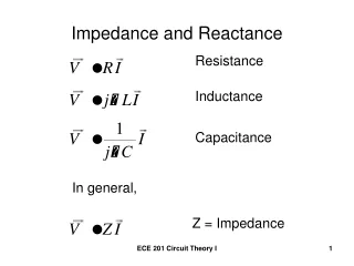
Impedance • AC steady-state analysis using phasors allows us to express the relationship between current and voltage using a formula that looks likes Ohm’s law: V = IZ • Z is called impedance. Lecture 21
Impedance • Resistor: • The impedance is R • Inductor: • The impedance is jwL Lecture 21
Impedance • Capacitor: • The impedance is 1/jwL Lecture 21
Some Thoughts on Impedance • Impedance depends on the frequency w. • Impedance is (often) a complex number. • Impedance is not a phasor (why?). • Impedance allows us to use the same solution techniques for AC steady state as we use for DC steady state. Lecture 21
Impedance Example:Single Loop Circuit w = 377 Find VC 20kW + + VC 10V 0 1mF - - Lecture 21
Impedance Example • How do we find VC? • First compute impedances for resistor and capacitor: ZR = 20kW= 20kW 0 ZC = 1/j (377 1mF) = 2.65kW -90 Lecture 21
Impedance Example 20kW 0 + + VC 2.65kW -90 10V 0 - - Lecture 21
Impedance Example Now use the voltage divider to find VC: Lecture 21
What happens when w changes? w = 10 Find VC 20kW + + VC 10V 0 1mF - - Lecture 21
+ 0.1mF 5mA 0 V 1kW - Low Pass Filter:A Single Node-pair Circuit Find v(t) for w=2p 3000 Lecture 21
Find Impedances + -j530kW 5mA 0 V 1kW - Lecture 21
+ 5mA 0 Zeq V - Find the Equivalent Impedance Lecture 21
Parallel Impedances Lecture 21
Computing V Lecture 21
+ 0.1mF 5mA 0 V 1kW - Change the Frequency Find v(t) for w=2p 455000 Lecture 21
+ -j3.5W 5mA 0 V 1kW - Find Impedances Lecture 21
+ 5mA 0 Zeq V - Find an Equivalent Impedance Lecture 21
Parallel Impedances Lecture 21
Computing V Lecture 21