Download

1 / 32
350 likes | 584 Views
Sequence Diagrams and Collaboration Diagrams . Rajkumar Buyya Grid Computing and Distributed Systems (GRIDS) Laboratory Dept. of Computer Science and Software Engineering University of Melbourne, Australia http://www.cs.mu.oz.au/~raj or http://www.buyya.com. Introduction/Agenda.

E N D
Sequence Diagramsand Collaboration Diagrams Rajkumar Buyya Grid Computing and Distributed Systems (GRIDS) Laboratory Dept. of Computer Science and Software Engineering University of Melbourne, Australia http://www.cs.mu.oz.au/~raj or http://www.buyya.com
Introduction/Agenda • Pieces of UML: • Structural Diagrams • Class and object diagram • Component and Deployment Diagram • Behavioural Diagrams • Use Case Diagram • Activity Diagram • Sequence Diagram • Collaboration Diagram • State Chart Diagram • Learned so far: • Use case diagram, class and object diagram, class relationships • Today we will focus on: • Sequence Diagram • Collaboration Diagram
Object Oriented Design • Design consists of the following steps : • Refine the class diagram. • Draw the interaction diagrams for the system. • Sequence Diagram • Collaboration Diagram • If objects go through complex state transitions – statechart diagrams • Do the above steps iteratively as needed.
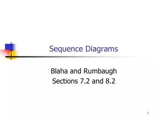
Sequence Diagram • Shows how objects communicate with each other over time. • That is, sequence diagrams are used to model object interactions arranged in time sequence and to distribute use case behavior to classes. • They can also be used to illustrate all the paths a particular use case can ultimately produce. • The sequence diagram consists ofActive Objects, Messages representedas solid-line arrows, andTime represented as a vertical progression.
:Name Sequence Diagram - Objects • A life line illustrates what is happening to an object in a chronological fashion. Object Life line Activation
Sequence Diagram – Time & Messages • Messages are used to illustrate communication between different active objects of a sequence diagram. :Name1 :Name2 Actor Message One Message Two
Types of Messages • Synchronous (flow interrupt until the message has completed. • Asynchronous (don’t wait for response) • Flat – no distinction between sysn/async • Return – control flow has returned to the caller.
Sequence Diagram – Compilation :Compiler Linker FileSystem Actor Compile Load Files Compile files Save OBJ Files Link Load OBJ files Link OBJ files Write EXE file
Branching Flow: flow goes to different objects [if condition is met] :Editor FileSystem Load File :BinaryViewer :TextViewer [text file] [binary file]
Alternative Flow: flow changes to alternative lifeline branch of the same object Editor FileSystem Actor Exit App [delete file] [save file]
Sequence diagram -example • Use case • Add Subject Use Case to URS (University Record System): • Scenario • Scenario 1 : Subject gets added successfully. • Scenario 2 : Adding the subject fails because the subject is already in the database.
System Design Principles • System input can take different forms. E.g. • From a graphical user interface • From a command file • URS system should be designed such that the functionality can be re-used. • Command reading and functionality implementation have to be separated.
Reading from a command file - example class URS{ public static void main(String[] args){ URSDatabase u = new URSDatabase(); //Read command from file; while ( not end of file) { u.procCommand(cmd); //Read next commad; } //Close file } }
u:URSDatabase procCmd(cmd) parseCommand(cmd) a:AddSubCmd << create >> [if cmdN = ADDSUB] AddSubCmd(u,cmdA) execute() Subject(id,name) sub1:Subject << create >> addSubject(sub1) Sequence Diagram – URS Add Subject Scenario {transient}
Creating and Deleting objects c:Client p: ODBProxy {transient} <<create>> :Transaction setAction(a, d, 0) setVales(a,d,3,4) committed <<destroy>>
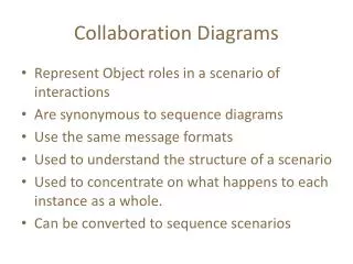
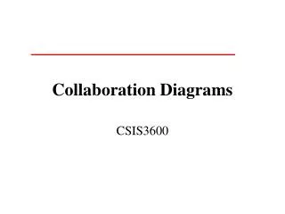
Collaboration Diagrams • Class diagrams indicates what classes are part of our system, what they offer, how they relate, but they don’t tell us how they communicate. • Collaboration diagrams show (used to model) how objects interact and their roles. • They are very similar to sequence diagrams. Actually they are considered as a cross between class and sequence diagram. • Sequence Diagrams are arranged according to Time. • Collaboration Diagrams represent the structural organization of object. • [Both sequence and collaboration diagrams are called interaction diagrams]
1:parseCommand(cmd) procCmd(cmd) a:AddSubCmd 2:[if cmdN = ADDSUB] AddSubCmd(u,cmdA) 3: execute() 3.2: addSubject(sub1) 3.1: Subject(id,name) {new} sub1:Subject Collaboration Diagram – URS Add Subject Scenario {transient} <<self>> u:URSDatabase {new} <<local>>
1:parseCommand(cmd) Collaboration Diagram – URS Add Subject Scenario <<self>> procCommand(cmd) u:URSDatabase class URSDatabase{ private String cmdN; private String cmdA; private parseCommand(String cmd){ cmdN = …. cmdA = …. } public procCommand(String cmd){ parseCommand(cmd); } }
Collaboration Diagram – URS Add Subject Scenario {transient} a:AddSubCmd u:URSDatabase 2: AddSubCmd(u,cmdA) {new} class URSDatabase{ private String cmdN; private String cmdA; public procCommand(String cmd){ parseCommand(cmd); if (cmdN == ADDSUB){ AddSubCmd a = new AddSubCmd(u,cmdA); } } }
Collaboration Diagram – URS Add Subject Scenario class abstract Command { protected String cmd; protected URSDatabase u; public abstract void execute(); } class AddSubCmd extends Command{ public AddSubCmd(URSDatabase urs, String cmd){ u = urs; // parse command and set the arguments } public void execute(){ // implement here } }
3: execute() Collaboration Diagram – URS Add Subject Scenario a:AddSubCmd u:URSDatabase <<local>> class URSDatabase{ private String cmd; public procCommand(String cmd){ parseCommand(0); if (cmd == ADDSUB){ AddSubcmd a = new AddSubCmd(……); } a.execute(); } }
3.1: Subject(id,name) sub1:Subject Collaboration Diagram – URS Add Subject Scenario a:AddSubCmd class AddSubCmd{ URSDatabase u; public execute(){ subject sub1 = new Subject(id,name); } }
3.2: addSubject(sub1) Collaboration Diagram – URS Add Subject Scenario a:AddSubCmd u:URSDatabase class AddSubCmd{ URSDatabse u; public execute(){ subject sub1 = new Subject(……); u.addSubject(sub1); } }
Collaboration Diagram – URS Add Subject Scenario class URSDatabase{ private String cmd; private Hashtable subjectHash = new HashTable(); public procCommand(String cmd){ parseCommand(0); if (cmd == ADDSUB){ AddSubcmd a = new AddSubCmd(……); } a.execute(); } public addSubject(Subject sub); { subjectHash.put(sub.getKey(), sub); } }
URS -High Level Class Diagram 1 has * teaches takes URSDatabase 1 has * UniversityMember Subject 0…10 0..3 AcademicStaff Student * 1
Collaboration Diagrams • Collaborations Diagrams show transient links that exists between objects. • <<self>> - A message from object to itself • << local>> - A message sent due to the object begin defined as a local variable in the method. • <<parameter>> -The object reference was sent as a parameter to the method. • <<global>> The object is global.
Use Case Vs Scenarios • Use case • Enroll Subject Use Case: • Scenario • Scenario 1 : Student is enrolled for the subject. • Scenario 2 : Enrollment fails since the student is already enrolled in 10 subjects.
stu:Student u:URSDatabase procCmd(cmd) parseCommand(cmd) {transient} a:AssgSubCmd << create >> execute() AssgSubCmd(u,cmdA) getStudent(id) return stu getSubject(subId) return sub addSubject(sub) Sequence Diagram – Enroll Student for subject successfully [if stu != NULL and sub != NULL]
1:parseCommand() {transient} <<self>> 2:AddSubCmd(u,cmdA) procCmd(cmd) a:AssgSubCmd {new} 3: execute() <<local>> 3.2: sub: = getSubject(subId) 3.1: stu: =getStudent(id) 3.3: [stu !=NULL and sub!= NULL]: addSubject(sub) stu:Student Collaboration Diagram – Enroll Student in Subject Scenario u:URSDatabase {parameter}
procCmd(cmd) 3: execute() <<local>> 3.2: sub: = getSubject(subId) 3.1: stu: =getStudent(id) 3.3: [stu !=NULL and sub!= NULL]: addSubject(sub) stu:Student Collaboration Diagram – Enroll Student in Subject subject - implementation {transient} {new} u:URSDatabase a:AssgSubCmd class AssgSubCmd{ private URSDatabase u; public execute(){ Student stu = u.getStudent(id); Subject sub = u.getSubject(subId); if (stu != null && sub != null){ stu.addSubject(sub); } } } {parameter}
stu:Student u:URSDatabase procCmd(cmd) parseCommand() {transient} a:AssgSubCmd << create >> execute() AssgSubCmd(u,cmd) [if stu != NULL and sub != NULL] getNumSubjects() addSubject(sub) return num [num >= 10] Excp return e Sequence Diagram – Enroll Student for subject - Failure