Download
1 / 34
350 likes | 373 Views
Machining Techniques. Dimensions, Tolerance, and Measurement Available Tools. Why Machine Stuff?. Research is by definition “off-road” frontier work into the unknown You can’t just buy all the parts mounting adapter between laser and telescope first-ever cryogenic image slicer

E N D
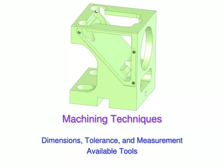
Machining Techniques Dimensions, Tolerance, and Measurement Available Tools
UCSD: Physics 121; 2012 Why Machine Stuff? • Research is by definition “off-road” • frontier work into the unknown • You can’t just buy all the parts • mounting adapter between laser and telescope • first-ever cryogenic image slicer • Although there are some exceptions • optical work often uses “tinker toy” mounts, optical components, and lasers • cryogenics often use a standard array of parts • biology, chemistry tend to use standardized lab equipment • Often you have to design and manufacture your own custom parts • learning about the capabilities will inform your design • otherwise designs may be impractical or expensive
UCSD: Physics 121; 2012 Critical Information • If you ask a machinist to make you a widget, they’ll ask: • what are the dimensions? • what are the tolerances? • huge impact on time/cost • what is the material? • impacts ease of machining • how many do you want? • when do you need it/them? • what budget does this go on? • at $50 to $80 an hour, you’d best be prepared to pay! • We’ll focus on the first two items
UCSD: Physics 121; 2012 Dimensions • You want to make a part that looks like the one above • How many dimensions need to be specified? • each linear dimension • each hole diameter (or thread type) • 2-d location of each hole • total: 22 numbers (7 linear, 5 holes, 10 hole positions)
UCSD: Physics 121; 2012 Notes on previous drawing • Some economy is used in dimensioning • repeated Φ0.129 diameter holes use 4 to denote 4 places • 4 1 • connected center marks on holes allow single dimension • 8 4 • Numbers in parentheses are for reference (redundant) • Dimension count: • 16 numbers on page • 6 linear plus 2 reference (don’t count) • 6 hole position, representing 10 • 2 hole descriptors, representing 5 • total information: 21 numbers (equal height of tabs implied) • note: depth mark on 0.129 holes is senseless • artifact of the way it was made in SolidWorks
UCSD: Physics 121; 2012 Standard views • In American (ANSI) standard, each view relates to the others on the page such that: • pick the “main” view • a view presented on the right of the main view is what that part would look like if you looked at the part from the right side of the main view • a view above the main view is how the part looks from above the main view • etc. • The examples on the right come from a good page: • http://pergatory.mit.edu/2.007/Resources/drawings/ • The international (ISO) standard is exactly opposite!!
UCSD: Physics 121; 2012 Tolerances • From the previous drawing, we see useful information in the title block • made from aluminum, only one, to be anodized (relevant for threads) • dimensions in inches; trust numbers, not drawing scale • .XX values held to 0.010 inches • .XXX values held to 0.002 inches
UCSD: Physics 121; 2012 Another example
UCSD: Physics 121; 2012 A closer look; #1 • New features: • radius spec. • angular spec. • counterbore spec. • detail (A) notation • Note different tolerances, alloy specification
UCSD: Physics 121; 2012 A closer look; #2 • New features: • depth spec. for tapped hole • countersink spec. • hidden lines (dashed)
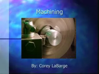
UCSD: Physics 121; 2012 Machining • The primary tools in a machine shop: • lathe: for cylindrically symmetric parts • part rotates, tool on x-y stage • milling machine (or mill): rectangular parts, hole patterns • spindle rotates tool, part on x-y-z stage • drill press: for low precision or chasing pilot holes • like a mill, except no fine motion control, thus no side-cut capability (a matter of holding strength as well as motion) • bandsaw: for roughing out stock • circular band of a saw blade makes for a continuous “hack saw” • sandpaper, files, granite block • grinding wheel (make lathe tools, diamond pins) • measurement equipment
UCSD: Physics 121; 2012 The Lathe
UCSD: Physics 121; 2012 Lathe Capabilities • Precision outer diameter • Precision inner diameter • Stepped and angled transitions • can drive tool at angle other than 90 • with numerical control, arbitrary profiles possible • Facing off • flat, or even conical • Threading (though complicated, advanced skill) • outer thread • inner thread • complete control over pitch, multi-thread, etc. • Boring • usually with drill bit (possibly followed by reamer) in tail stock • but can use boring bar to make larger holes
UCSD: Physics 121; 2012 Lathe Tools The canonical lathe tool: dimensions depend on material being worked
UCSD: Physics 121; 2012 Lathe Tools, continued a “boring bar” lets you get deep inside a part for making an inner diameter (for holes larger than available drill bits & reamers) lathe tools are usually shaped by the machinist using a grinding wheel
UCSD: Physics 121; 2012 “A Rudimentary Lathe”
UCSD: Physics 121; 2012 The Milling Machine
UCSD: Physics 121; 2012 Milling Machine Capabilities • Surfacing/Shaping • fly cutting; facing edges • Pockets • tightness of corners depends on diameter of bit • Slots • Hole Patterns • with table encoders, easily get to 0.001 inch (25 microns) • With numerical control, arbitrary shapes/cutouts • gets around etch-a-sketch problem: can draw circles, etc.! • Simple and Complex Angles • Boring (can use boring bar here, too)
UCSD: Physics 121; 2012 Mill Bits • square end-mills are the workhorse bits: • pockets • slots • edge trim • facing This device holds a lathe- like tool bit to become a fly-cutter, for surfacing large flat faces ball-end mills make rounded pockets or spherical pockets; also fillets corner-rounders form rounded corners! conical end-mill for chamfers graphics from McMaster Carr online catalog: www.mcmaster.com
UCSD: Physics 121; 2012 Drills and Reamers standard “jobber” drill: will flex/walk, follow pilot stub drill for less walk/greater rigidity center drill establishes hole position with no walk reamers (straight or spiral) finish off hole (last several thousandths) precise hole diameter for insertion of dowel pins, bearings, etc. plunge while spinning, extract still countersink: for screw heads & deburring hole graphics from McMaster Carr online catalog: www.mcmaster.com
UCSD: Physics 121; 2012 Drilling Practices • Drills come in fractional inches, metric, and a standard wire gauge index • wire gauge index is most common in U.S.: most finely graded • see http://www.carbidedepot.com/formulas-drillsize.htm • Drills walk when pushed into unbroken surface • must use a punch to establish a conical defect for drill to find • or use a center drill (no walk) to get the hole started • stub drills better than jobber, but not as good as center drill • Use pilot hole for larger holes • especially if precision important: use several steps so drills primarily working on walls
Taps thread holes, after pre-drilling to the specified diameter Taper tap for most applications Plug tap for getting more thread in bottomed hole preferably after taper already run Bottom tap for getting as many threads as possible in bottomed hole preferably after plug already run Dies for outside thread: seldom used buy your screws & threaded rod!! UCSD: Physics 121; 2012 Taps and Dies: making threads some graphics from McMaster Carr online catalog: www.mcmaster.com
UCSD: Physics 121; 2012 Example Procedure • Final part outer dimensions are 1.5500.7550.100 • so find 1/8-inch aluminum stock and cut on bandsaw to something bigger than 1.6250.8125 (1 5/8 by 13/16) • de-burr edges with file or belt sander • Establish outer dimensions • get 0.755 dimension • put in mill table vice on parallels, part sticking about 0.1 inches above jaws
UCSD: Physics 121; 2012 Procedure, cont. • end-mill exposed (up-facing) face until all low spots gone, taking multiple passes at about 0.010 inches per pass • de-burr and rotate 180 in jaw about horizontal axis • end-mill new side (opposite first) until low spots gone • de-burr and measure; figure out amount remaining to cut • place back in vice, either finished side up • bring up knee until end-mill just touches and set knee dial to zero • make successive passes, bringing up knee until the prescribed amount has been removed • measure to make sure • get 1.55 dimension • place in jaw with large face up, rough edge extending beyond jaw side • use side of end-mill to shave edge; traveling in direction of cut (conventional cut) • once low spots done, cut opposite direction for smooth finish (climb cut) • de-burr, and rotate 180 about vertical axis, rough edge sticking out • smooth out this surface, measure (maybe even in place), and do final trims to bring it into spec.; de-burr
UCSD: Physics 121; 2012 Procedure, cont. • get 0.100 dimension • center in jaw, with guaranteed > 0.030 above jaw: machining into vice is very bad: NEVER let the tool touch the jaw! • use large-ish end-mill or even fly-cutter to take down surface by 0.010; take out and de-burr • flip part to remove other side (skin) by an additional 0.015, measuring before final cut (in place, if possible) • Establish hole pattern • leaving in place, establish coordinate origin • use edge-finder to get edge positions, resetting encoders to zero at edge-finder jump • remember to account for 0.100 edge-finder radius (need to re-zero at 0.100 in appropriate direction) • center drill each hole position • use small center drill, in collet if possible (rather than chuck) • at each coordinate pair, run in center drill as far as you can without exceeding final hole size
UCSD: Physics 121; 2012 Procedure, cont. • drill holes • use #30 drill on four holes • use #29 drill for 8-32 pre-tap • see http://www3.telus.net/public/aschoepp/tapdrill.html • take part out and de-burr holes (with countersink in hand) • Cut two notches out • place part in vice so that the tab that will remain is completely free of vice jaws • use edge-finder to establish left-right origin • measure end-mill diameter carefully (maximum extent of teeth) • work out x-positions corresponding to full cut on both sides • bring up knee to touch material, set to zero • with end-mill off to side, bring up knee 0.400 inches (usu. 4.00 turns of crank)
UCSD: Physics 121; 2012 Procedure, cont. • begin swiping 0.020 at a time off of edges until you are 0.005 from designated stopping points • move end-mill to side so that final travel will be against blade direction for best finish (climb cut) • bring up knee by final 0.005 • go final 0.005 in x-direction for final cut • make final cut, then walk away in x to finish bottom cut • end-mills cannot be plunged unless material at center of end-mill is already cleared out: they aren’t drills • Tap 8-32 hole with taper tap • Final de-burr, final measurement check • Clean part, check fit to mating piece(s)
UCSD: Physics 121; 2012 Measurement Tools • General Purpose Caliper • Micrometer • reading a micrometer: • http://feh.eng.ohio-state.edu/Tutorials/micrometer/reading.html • Dial Indicator • Depth Micrometers • Cleaning is a very important part of measurement
UCSD: Physics 121; 2012 Intro to SolidWorks
UCSD: Physics 121; 2012 SolidWorks Overview • SolidWorks is a totally fantastic design package that allows: • full 3-D “virtual” construction/machining • excellent visualization: rendering and rotation • feedback on when enough dimensions are established • parameters such as volume, mass, etc. • conversion from 3-D to 2-D machine drawings • assembly of individual parts into full assemblies • warnings on interferences between parts in assemblies • Typical sequence: • 2-D sketch in some reference plane, with dimensions • extrude sketch into 3-D • sketches on surface, followed by extrude or cut, etc.
UCSD: Physics 121; 2012 Our Exposure to SolidWorks • Computers in lab have SolidWorks on them • Pick a machining piece you want to model • or find/dream-up your own, but be careful to pick appropriate difficulty level • if it’s your own creation, you must describe its purpose • Measure relevant dimensions of piece to model • Go through SW online tutorials until you have enough knowledge to make your 3-D model • Make 3-D model, and turn this into 2-D machine drawing • with dimensions in “design” units and appropriate tolerances
UCSD: Physics 121; 2012 Assignments • Reading from Chapter 1: • (black = 3rd ed.; red = 4th) • sec. 1.1 except 1.1.8; sec. 1.1 except 1.1.8 • sec. 1.2; secs 1.2, 1.3 • secs, 1.3.4–1.3.8; secs 1.4.1–1.4.4, 1.4.8 • sec. 1.4;sec 1.5 • SolidWorks Tutorial & part emulation, including: • 3-D part, matching measurements • 2-D drawing a machinist would enjoy • description of part function, if not a pre-made part • brief write-up including difficulties overcome, estimated mass (from SolidWorks model), and a brief description of how one would make the part—roughly at level of second indentation (dash) in lecture detail of the example part • see website for (definitive) lab instructions/details