Download
1 / 25
250 likes | 439 Views
Non-destructive testing using magneto-resistive sensors. David P. Pappas Quantum Devices Group National Institute of Standards and Technology Boulder, CO, 80305 A. Nazarov, Fabio da Silva NIST Ken Marr, Jim Ryan FBI Audio Lab Erin Gormley, Jim Cash NTSB Dave Krefft NSA.

E N D
Non-destructive testing using magneto-resistive sensors David P. Pappas Quantum Devices Group National Institute of Standards and Technology Boulder, CO, 80305 A. Nazarov, Fabio da Silva NIST Ken Marr, Jim Ryan FBI Audio Lab Erin Gormley, Jim Cash NTSB Dave Krefft NSA
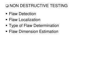
Objectives • Develop state-of-the art magnetic imaging metrology for NIST • Forensics • Bio-magnetic tag detection • Component failure analysis • Non-destructive testing • Probe components non-destructively to determine: • Power usage • Defects • Design flaws • Unapproved process • Investigate low level signal monitoring • Wafer level • De-processed devices
Procedure • Methods: • Map out magnetic field above device under test (DUT). • Single, scanned magneto-resistive (MR) element. • Array of elements (faster). • DUT • Test artifacts – striplines, etc. • Sample chips – processed, deprocessed & flip-chip • Invert the magnetic field to find current distribution. • Metrics • Low frequency current resolution: • Limited by noise floor of sensor - field falls off as 1/d from DUT. • Spatial resolution: • Deconvolution requires close proximity to DUT, low noise. • Temporal resolution – High frequency • Johnson & shot noise of resistors increases with bandwidth.
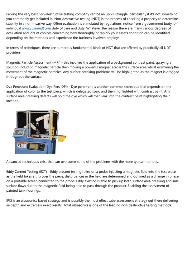
Magnetic imaging system • x-y-z translation stage • Stationary sample • Lock-in amplifier • Unshielded magnetic sensor – 1 mm resolution • AMR, GMR sensor mounted on flexure • Self aligning - slides on back of Si wafer • Sensors readily available • Scalable, arrayable, fast
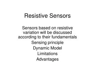
* * * * Magneto-resistive (MR) sensors I • AMR - Anisotropic MR • Single ferromagnetic film NiFe • 2% change in resistance • Spintronic: • GMR trilayer w/NM spacer • 60% DR/Rmin Co/Cu/Co • “Spin Valve” • TMR – Insulator spacer • 500% DR/Rmin at R.T. • CoFeB/MgO/CoFeB • Hayakawa, APL (2006) M FM NM FM
I+ I- I- V+ V- 16 mm x 256 4 mm Cassette Tape – forensic analysis write head stop event erase head stop event 45 mm Large arrays of MR sensors • NDE Imaging applications • 256 element AMR linear array • Thermally balanced bridges • High speed magnetic tape imaging – forensics, archival applications 4 mm BARC.
Magnetic field measurement of current MR element - Localized Current, I IB B-field Z (up) BZ x y Coordinate system
Magnetic field probe above meander line test structure 1 mm • 10 mm meander line • 5 mA current • Spacing = 1000 mm • Sensor 100 mm above sample BZ 8 x 8 mm, Bz –field image
Lockin Amplifier data acquisition +-10 mA in line @ 15 kHz, 1 ms 10 mm wide meander Image magnetic field of test stripline sample Cross section scan
Deconvolution of planar currents from magnetic fields z Localized current in y direction Measure Bz Height = z0 z0 x Bz 1/x Transform method Chatraphorn, et. al (2000): x=+z0 X -z0
Measured magnetic field image of test stripline Calculated currents Calculate currents from Bz +dB/dy y -dB/dx +dB/dx x -dB/dy
Non-destructive VLSI current measurement • Intel flip-chip RAM • Wafer thinned • Had been probed with FIB from back • Short circuit induced in center • Q – Could we locate short circuit?
Intel flip-chip RAM with short height = wafer thickness (~500 mm) Calculated currents Measured magnetic field - Bz +Jx y +Jy -Jy x -Jx
z < g Spatial resolution “From what height can we resolve two currents that are flowing in the same direction?” sensor z >> g B Z gap
Spatial resolution • In principle, deconvolution is perfect • d-functions in, d-functions out • Works for any current distribution • Multiple sources, gnd planes • In real life: • Smaller signal for large z • Noise – electronic & mechanical z >> g
Test structures for spatial resolution current Split meander line: • I = 65 mA • g = 200,100, 50,20,10, 5 mm • Z = 500 and 100 mm g (mm) Resolves g ~ z/10 z=500 mm z=100 mm
DV = 1 mV MR elements as real-time, non-contact probes Expected signal from stripline I = 7 mA, d = 1 mm Signal from stripline with z~0 7 mA pulse Gain = 1000 Single sweep
High frequency operation of probes - f >100 kHz Sample & Average 6 ms pulse • Intrinsic sensor response ~GHz • Filtering slows response • Random noise – can be averaged out: • Johnson - • Shot - • 1/f -neglible- • => noise Average 1000 sweeps
Present & Future Applications • Probes • Non-destructive, localized current mapping • Monitoring of individual current lines • Spatial, temporal resolution determined by • probe height • Sensitivity • signal strength • Sampling (real-time vs. averaging) • Linear & two-dimensional arrays • Field mapping • VLSI failure analysis • Listen in on high frequency chip emissions • Localization, analysis • Want gold standards for chip emissions to compare
For non-localized, planar source • Ground planes, power, … • Width of trace greater than height, size of sensor • w >> z0 • Bx = constant over current • ~ 0 outside • Bz = 0 over current • ~1/x outside current x-sensor Current in plane z-sensor h w B Bx Bz x B field
Use artifact with both types of currents Asymmetric stripline 50 mm wide line with ground plane, 100 mA, 1 kHz 50 W Field distribution – Bz Deconvoluted current - Iy
In-plane field current measurements Deconvoluted current -Iy Field distribution - Bx Ideal geometry for magneto-resistive arrays Use either BX & BZ sensor arrays 2 – dimensional image
Sensitivity of MR vs. SQUID Signal: Resistive noise : (50 ohm, Johnson) Bz Small area 1 x .05 mm Tiny flux Roth, et. al Chatraphorn, et. al Large area >20 x 20 mm Big flux • Flux = • MR elements comparable to SQUIDS in flux measurement
Test structure with features 2 mm hole 1 mm I 0.5 mm (b) (a) Asymmetric meander line With holes in return plane BZ at z = 1 mm
Current distributions calculated for asymmetric stripline Feature resolution optimal for z ~ d/2