Download
1 / 24
740 likes | 2.17k Views
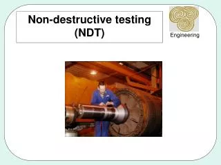
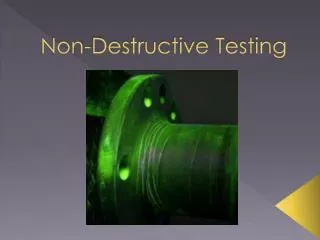
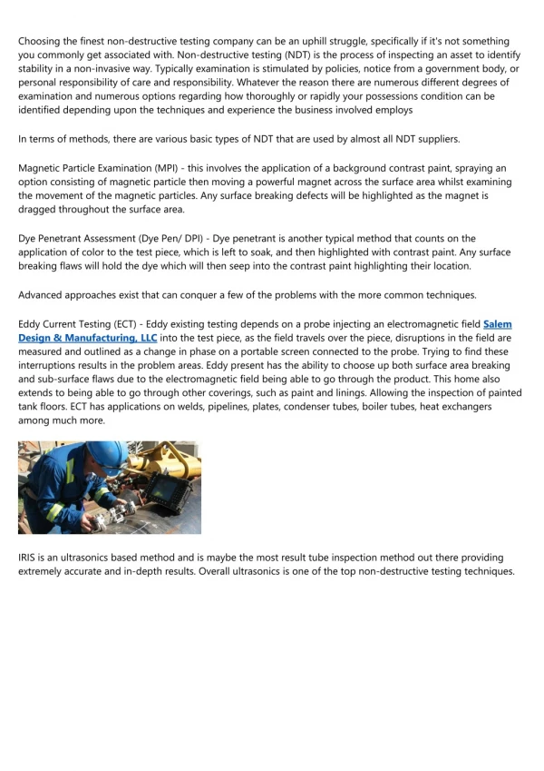
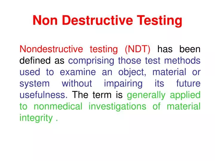
Non Destructive Testing. Nondestructive testing (NDT) has been defined as comprising those test methods used to examine an object, material or system without impairing its future usefulness. The term is generally applied to nonmedical investigations of material integrity . .

E N D
Non Destructive Testing Nondestructive testing (NDT) has been defined as comprising those test methods used to examine an object, material or system without impairing its future usefulness. The term is generally applied to nonmedical investigations of material integrity.
Applied directly to the product Tested parts are not damaged Various tests can be performed on the same product Specimen preparation not required Can be performed on parts that are in service Low time consumption Low labour cost Characteristics of NDT
Objectives of NDT • to ensure product integrity, and in turn, reliability; • To detect internal or surface flaws • To measure the dimensions of materials • To determine the materials’ structure • To evaluate the physical and mechanical properties of materials • to avoid failures, prevent accidents and save human life; • to make a profit for the user; • to ensure customer satisfaction and maintain the manufacturer's reputation; • to aid in better product design; • to control manufacturing processes; • to lower manufacturing costs; • to maintain uniform quality level; • to ensure operational readiness.
Aspects / Factors in NDT Method • Energy source or medium used to probe the test object (such as X-rays, ultrasonic waves or thermal radiation); • Nature of the signals, image or signature resulting from interaction with the test object (attenuation of X-rays or reflection of ultrasound, for example); • Means of detecting or sensing resulting signals (photo emulsion, piezoelectric crystal or inductance coil); • Method of indicating or recording signals (meter deflection, oscilloscope trace or radiograph); and • Basis for interpreting the results (direct or indirect indication, qualitative or quantitative, and pertinent dependencies).
NDT Methods • Visual Inspection • Liquid penetrant method • Ultrasonic Inspection • Radiography methods • X-ray radiography & fluoroscopy • γ- ray radiography • Eddy current testing • Magnetic particle testing • Thermography
LIQUID PENETRANT METHOD Principle A liquid penetrant is applied at the surface of the specimen. The penetrant is drawn by the surface flaws due to capillary action and this is subsequently revealed by a developer, in addition with visual inspection. Procedure • Cleaning the surface • Application of the penetrant • Removal of excess penetrant • Developing • Inspection
Penetrant Chemical stability & uniform physical consitency High degree of wettability Quick & complete penetrability Low viscosity Sufficient brightness & permanence of colour Chemical inertness Low toxicity Slow drying Ease of removal Low cost Developer Highly absorptive Fine grain size & particle shape for easy dispersion Provision of contrast background Easy application Formation of thin uniform coating over surface Easily wettable Low toxicity Characteristics of a penetrant & a developer
Applications • Turbine rotor discs & blades • Aircraft wheels, castings, forged components, welded assemblies • Automotive parts – pistons, cylinders, etc. • Bogie frames of railway locomotives & rolling stock • Electrical ceramic parts – spark plug insulators, glass-to-metal seals, etc. • Moulded plastic parts
ADVANTAGES Simple & inexpensive Versatile & portable Applicable to ferrous, non-ferrous, non-magnetic & complex shaped materials which are non-porous & of any dimension Detects cracks, seams, lack of bonding, etc. LIMITATIONS Detect surface flaws Non-porous surface for material Surface cleaning before & after inspection Deformed surfaces & surface coatings prevent detection Advantages & Limitations of Liquid Penetrant Method
Principle Whenever there is a change in the medium, the ultrasonic waves are reflected. Thus, from the intensity of the reflected echoes, the flaws are detected without destroying the material. ULTRASONIC FLAW DETECTION Block Diagram for an Ultrasonic Flaw Detector Master Timer Time Base Amplifier Y Signal Pulse Generator X CRT Echo Signal Amplifier Probe (Transducer) Work piece
Applications • Quality control & material inspection • Detection of failure of rail rolling stock axes, pressure columns, earthmoving equipments, mill rolls, mixing equipments, etc. • Measurement of metal section thickness • Thickness measurements – refinery & chemical processing equipments, submarine hulls, aircraft sections, pressure vessels, etc. • Inspect pipe & plate welds • Inspect pins, bolts & shafts for cracks • Detect internal corrosion
Advantages Sensitive to surface & subsurface discontinuities Superior depth of penetration for flaw detection High accuracy – position, size & shape of defect Minimal part preparation Instantaneous result Automated detailed images Non hazardous Portable Limitations Surface accessibility for ultrasonic transmission Highly skilled & trained manpower Irregular, rough, coarse grained or non homogenous parts, linear defects oriented parallel to the beam cannot be inspected – low transmission & high noise Coupling medium required Reference standards – equipment calibration & flaw characterization Advantages & Limitations
Applications • Measurement of velocity of fluids through pipes • Three dimensional image of specimen obtained • Detect corrosion in pipes and pressure vessels
Radiography The formation of an image of the test piece either on a photographic film or on a fluorescent screen due to x-rays or γ-rays passing through the test piece. Law of Absorption of X-rays
X-RAY RADIOGRAPHY Principle X-rays are passed through the specimen under inspection and it is differentially absorbed by the specimen. The transmitted x-rays are received by the photographic film and the film is developed. The dark and light shadows reveal the defects present in the specimen and hence the defects are defected.
X-RAY RADIOGRAPHY – Displacement Method Principle X-rays are exposed over the specimen by keeping the x-ray source at position ‘A’ and then at ‘B’ by displacing the source through a certain distance. The images are recorded at positions ‘A’ and ‘B’. From the displacements of the x-ray tube and the images, the exact position of the defect can be determined.
MERITS Material suitability Used on castings and weldings Determination of thickness Used on uneven surfaces Time consumption is less Permanent record DEMERITS Expensive Development time consumption large Skilled & trained personnel required Tissue damage due to radiations Merits & Demerits of X-ray Displacement Method
X-RAY FLUOROSCOPY Principle X-rays are passed through the specimen and is made to fall on a fluorescent screen. With respect to the defects in the specimen, there will be a variation in intensity.
Merits No need of washing and developing films Low cost Image viewed immediately on screen Time consumption is less Movement of defects detected (real time images) Permanent record can be made Demerits Poor resolution Low image contrast Electronic image intensifier required for increasing the contrast MERITS & DEMERITS
Radiography Image developed on photographic film High resolution & contrast Immediate image cannot be obtained. X-ray energy is converted into chemical energy. Expensive Time consumption is high. Fluoroscopy Image is developed on fluorescent screen. Fair resolution and low contrast. Immediate image can be viewed through the monitor. X-ray energy is converted into visible light. Inexpensive. Time consumption is low Differences