Download
1 / 52
550 likes | 1.04k Views
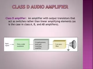
Audio Amplifier with Equalizer. Project #33 Bryan McDevitt Jason Ohnemus Peter Keenan TA – Julio Urbina Thursday April 27, 2000. Audio Amplifier with Equalizer. Introduction Our purpose was to design an audio amplifier with equalizer

E N D
Audio Amplifier with Equalizer Project #33 Bryan McDevitt Jason Ohnemus Peter Keenan TA – Julio Urbina Thursday April 27, 2000
Audio Amplifier with Equalizer • Introduction • Our purpose was to design an audio amplifier with equalizer • Our goals were to have around 20W output power while trying to minimize noise • To gain experience in design and construction of general electrical circuitry
Audio Amplifier with Equalizer • Three different subprojects • Graphic Equalizer utilizing frequency filters • Amplifier built and designed at the transistor level • Power supply with the attempt to minimize noise from ac outlet
Graphic Equalizer • Design Considerations • Analog or Digital • filter type • Butterworth or Chebyshev • Filter order • frequency ranges of each band
Graphic Equalizer • Assemble 5 filters over the various bands • Input the signal into each filter • Use trimpots to attenuate signal on desired band • Sum the signals together before going into the amplifier
Graphic Equalizer • Low Pass Filter topology • Band Pass Filter topology
Graphic Equalizer • Standard Equations used (from ECE353 Supplementary Notes - Spring 2000 by Professor Steve Franke)
Graphic Equalizer • To test the analog design, used an oscilloscope • compared the input amplitude from a function generator to the output of each band • analog filters did not seem to achieve both passband gain levels and stopband attenuation levels desired • decided to try digital filters using a DSP
Graphic Equalizer • Used FIR filters for each band • Obtained coefficients using the Matlab command remez to get Parks-McClellan filters • Tested using oscilloscope and observed desirable attenuation in stopbands and acceptable gain in passbands
Graphic Equalizer • Input Wave to DSP (50mV wave at 2kHz)
Graphic Equalizer • Output Wave from DSP (50mV at 2kHz)
Audio Amplifier Design Considerations • Output Power • Efficiency • Noise
Audio Amplifier Amplifier • Advantages of single-ended as opposed to differential amplifier • Single ended can be sent straight to output • Differential allows for more common power supply • Slightly more power with differential • Don’t have worry as much about noise with fewer stages
Audio Amplifier • Enough gain so that 20W output can be achieved • Really didn’t need more than one stage due to size of input signal
Audio Amplifier • Output Stage • Class A, B, AB • Class A – least efficient, least noise • Class B – most efficient, most noise • Class AB – average efficiency, average noise • Must be efficient enough to deliver 20W of power to speakers
Audio Amplifier • Problem 1 - Using single ended diff amp caused half of the output waveform to be clipped. • Solution - Adjusted power supply so that waveform is shifted above where it was clipped
Audio Amplifier • Problem 2 - Amplitude of original signal was too small so a lot of noise was being introduced • Solution - Doubled amplitude of input signal and reduced overall gain of the circuit
Power Supplies • Design Overview Transformer Rectifier Filter Regulator AC Line from wall Load
Power Supplies • Design Overview • Transformer used to stepdown 120V, 60Hz AC to a lower voltage • Rectifier used to eliminate negative portion of the sinusoidal AC • Filter used to Keep voltage at desired levels • Regulator used to designate actual voltage level
Power Supplies • Transformer Options • Two types of transformers are usually used in power supplies • single-ended secondary • center-tapped secondary • both step 120V down to 25.2 • Using the center-tapped secondary transformer because of availability
Power Supplies • Rectifier Options • Two basic types of rectifiers are usually used • half-wave rectifier • full-wave rectifier
Power Supplies • Rectifier Options • Half-Wave Rectifier • Circuit Setup
Power Supplies • Rectifier Options • Half-Wave Rectifier • Voltage/Time Plot
Power Supplies • Rectifier Options • Full-Wave Rectifier • Circuit Setup
Power Supplies • Rectifier Options • Full-Wave Rectifier • Voltage/Time Plot
Power Supplies • Obviously Full-Wave rectification is a better choice • less time between peaks • means less time for capacitor to discharge • adds up to less of a ripple voltage • closer to DC • less noise
Power Supplies • Rectifier Options • Final decision on Rectifier • Full-Wave Bridge Rectifier
Power Supplies • Rectifier Options • Full-Wave Bridge Rectifier • provides electrical isolation between AC powerline and the rectifier output • can be used with either center-tapped or single-ended secondary winding transformers • when used with center-tapped can produce power supply with voltage twice that of each transformer end
Power Supplies • Over all Design Options • Have decided on type of rectifier • Transformer type is set because of availability • center-tapped • Next step is to build the regulator • this means deciding on a needed DC voltage and a corresponding zener diode
Power Supply • Regulator • regulator sets output voltage • consists of two components • zener diode (to set voltage out) • resistor (to limit current through the zener) From filter and rectifier
Power Supplies • Graph with regulator in place
Power Supplies • Overall design • We now have all the components except for the filter • As can be seen on the last slide we the voltage set, but there still is approx. a 6.5 Volt ripple • Designing the filter correctly will ensure a small ripple voltage
Power Supplies • Filter Design • Filter is made up of one capacitor • Decide what is an acceptable ripple voltage • from that get capacitor value needed • we used a ripple voltage of 0.5% of desired voltage • Vripp (6.2V supply) = 31 mV • Vripp (25 V supply) = 125 mV
Power Supplies • PSpice schematic with all modules in place
Power Supplies • PSpice simulation
Power Supplies • PSpice ripple voltage
Power Supplies • Now let’s look at some actual data taken with an oscilloscope and HP-Vee. • You should notice that the Vpp is higher than PSpice ripple voltage • noise • non-ideal parts
Power Supplies • Ripple voltages are higher than in simulations, but still within the 0.5% of desired output voltage • Shorter lead lengths and sheilding for the circuit would help reduce the noise