Download
1 / 29
310 likes | 561 Views
Correction of Geometric Distortions in Line Scanner Imagery. Peter Kopacz Dr. John Schott Bryce Nordgren Scott Brown May 8, 1998. Coverage. Line Scanner Background Theory Geometric Distortions Results Future Work / Recommendations. IFOV. along track. FOV. across track.

E N D
Correction of Geometric Distortions in Line Scanner Imagery Peter Kopacz Dr. John Schott Bryce Nordgren Scott Brown May 8, 1998
Coverage • Line Scanner Background Theory • Geometric Distortions • Results • Future Work / Recommendations
IFOV along track FOV across track sampled ground pixel Line Scanner Example • Airborne / Spaceborne EO Imaging Instrument • Scanning mirror allows for collection of ground data one line at a time geometric distortions...
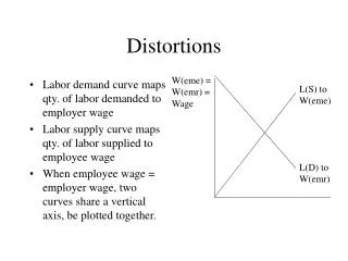
Geometric Distortions • Degradation in visual appearance of the image • Due to the Platform Attitude (orientation): • Roll, Pitch, and Yaw • Due to the Sensor’s Design Characteristics: • Tangential, V/H roll distortion….
Roll Distortion Roll Distortion introduces a shift in the acquired scan lines. tangent distortion….
Tangent Distortion - All pixels collected at equal angular increments. - Unequal ground representation between the collected ground pixels (Dedge > Dnadir) V/H distortion….
V/H Distortion • V/H - ratio of aircraft velocity and altitude • oversampling - scan rate is too fast when compared to the ratio • undersampling - scan rate is too slow when compared to the ratio Oversampling….
V/H Distortion - oversampling Scan lines are acquired too fast, causing an overlap Undersampling….
V/H Distortion - undersampling Scan lines are acquired too slow, leaving gaps proposed hypothesis….
Hypothesis Develop a set of C algorithms to correct the discussed geometric distortions in line scanner imagery. Research Progress….
Uncorrected Input Scan Parameters 512 scan lines 512 pixels per line altitude = 1000 ft Field of View = 45o 512 512
Corrected Output 334 551 • Roll Correction - (shifting of scan lines rectifies the image) • V/H Correction - (eliminated the stretching in scene objects) • Tangent Correction - (pixels represent equal ground areas)
Histogram Comparison Input Image (512 x 512) Output Image (551 x 334) • Nearest Neighbor Resampling • Mean Radiometry (DC Distribution) Preserved
Uncorrected Input Scan Parameters 512 scan lines 512 pixels per line altitude = 250 ft Field of View = 45o 512 Distortions: V/H (Undersampling) Tangent 512
Corrected Output • V/H Correction - (eliminated compression effects in scene objects) • Tangent Correction - (pixels represent equal ground areas) • Equal ground representation along and across track (square ground pixels) 1336 541
Histogram Comparison Input Image (512 x 512) Output Image (541 x 1336) • Nearest Neighbor Resampling • Mean Radiometry (DC) Preserved Research Progress….
Uncorrected Input Scan Parameters 512 scan lines 512 pixels per line altitude = 250 ft Field of View = 45o slant path (45 degrees) 512 Distortions: V/H (Undersampling) Tangent (ex:curvature along the diagonal) 512
Corrected Output • V/H Correction - (eliminated compression effects in scene objects) • Tangent Correction - (pixels represent equal ground areas) • Improvement in the appearance of the diagonal 615 1025
Algorithm Improvements • Single resampling after Roll, Tangent, and V/H corrections limits further image degradation (ex: blurring due to bilinear resampling) • Choice of Resampling Algorithms: • Nearest Neighbor or Bilinear • Corrects multiple bands simultaneously Error Analysis….
Scientific Analysis • accurate determination of ground pixel’s position dictates the appearance of the resulting image. • determines which flight parameters are the largest sources of error : aircraft velocity, aircraft altitude, roll angle, start angle, IFOV? How ? ...
Error Sensitivity Analysis Based on the governing equations, estimate the errors across track (X) and along track (Y) Error Across Track….
IFOV H qstart + qroll Error Across Track ground pixel ctr[x] = H * tan ( qstart + qroll + (IFOV*x) + (IFOV/2) ) Plots….
Roll Angle Effects • Largest source of error across track • Sensor’s ability to accurately determine a ground pixel’s position decreases for pixels near the edges
Altitude Effects • Second Largest source of error across track • Nadir pixel unaffected by the sources of error Error Along Track….
Error Along Track H n * Dy= n * ( (H *IFOV) - (Velocity * time_per_scan) ) Plots….
Velocity Effects • Largest source of error along track • Position Error increases with aircraft velocity
Altitude Effects • Second Largest source of error along track Future Work….
Conclusion - Future Work • Correction algorithms successfully improve the visual appearance of the image • Incorporate the algorithms with (MISI) line scanner • Incorporate other geometric distortions, such as pitch and yaw Acknowledgments….
Acknowledgments • I’d like to thank the following people for contributing to this research: • Dr. John Schott • Bryce Nordgren • Scott Brown • Rolando Raqueño www.cis.rit.edu/~pak2930