Download
1 / 36
360 likes | 575 Views
Unit 9 Multiplexers, Decoders, and Programmable Logic Devices. Ku-Yaw Chang canseco@mail.dyu.edu.tw Assistant Professor, Department of Computer Science and Information Engineering Da-Yeh University. Contents. 9.1 Introduction 9.2 Multiplexers 9.3 Three-State Buffers

E N D
Unit 9Multiplexers, Decoders, and Programmable Logic Devices Ku-Yaw Chang canseco@mail.dyu.edu.tw Assistant Professor, Department of Computer Science and Information Engineering Da-Yeh University
Contents 9.1 Introduction 9.2 Multiplexers 9.3 Three-State Buffers 9.4 Decoders and Encoders 9.5 Read-Only Memories 9.6 Programmable Logic Devices 9.7 Complex Programmable Logic Devices 9.8 Field Programmable Gate Arrays Fundamentals of Logic Design
Programmable Logic Devices • A general name for a digital integrated circuit capable of being programmed to provide a variety of different logic functions Fundamentals of Logic Design
Programmable Logic Arrays • Performs the same basic function as a ROM • n inputs and m outputs • m functions of n variables • Differences in internal organization • The decoder is replaced with an AND array • OR array • PLA : a sum-of-product expression • ROM : truth table Fundamentals of Logic Design
PLA Structure Fundamentals of Logic Design
PLA with Three Inputs, Five Product Terms, and Four Outputs Fundamentals of Logic Design
AND-OR Array Fundamentals of Logic Design
PLA Table Fundamentals of Logic Design
PLA Realization • f1 = a’bd + abd + ab’c’ + b’c • f2 = c + a’bd • f3 = bc + ab’c’ + abd Fundamentals of Logic Design
PLA Structure Fundamentals of Logic Design
PLA Table v.s. Truth Table • PLA Table • Each row represents a general product term. • 0, 1, or more rows may be selected. • ROM Truth Table • Each row represents a minterm. • Exactly one row will be selected. Fundamentals of Logic Design
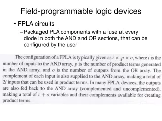
PLAs • Mask-programmable PLAs • Programmed at the time of manufacture • Similar to mask-programmable ROM • Field-programmable PLAs (FPLAs) • Use electronic charges to store a pattern in the AND and OR arrays • An FPLA with 16 inputs, 48 product terms and 8 outputs • 8 functions of 16 variables • Total number of product terms does not exceed 48 Fundamentals of Logic Design
Programmable Array Logic • PAL • a special case of PLA • AND array is programmable • OR array is fixed • Less expensive • Easier to program Fundamentals of Logic Design
PAL • A buffer is used • To drive many AND gate inputs Fundamentals of Logic Design
PAL • Connections to the AND gate inputs are represented by X’s Fundamentals of Logic Design
PAL segment Fundamentals of Logic Design
Full Adder • The logic equations for the full adder are Sum = X’Y’Cin + X’YC’in + XY’C’in + XYCin Cout = XCin + YCin + XY Fundamentals of Logic Design
Full Adder Fundamentals of Logic Design
Contents 9.1 Introduction 9.2 Multiplexers 9.3 Three-State Buffers 9.4 Decoders and Encoders 9.5 Read-Only Memories 9.6 Programmable Logic Devices 9.7 Complex Programmable Logic Devices 9.8 Field Programmable Gate Arrays Fundamentals of Logic Design
CPLDs • As integrated circuit technology continues to improve, more and more gates can be placed on a single chip. • Complex Programmable Logic Devices (CPLDs) • When storage elements such as flip-flops are also included on the same IC, a small digital system can be implemented with a single CPLD. Fundamentals of Logic Design
Contents 9.1 Introduction 9.2 Multiplexers 9.3 Three-State Buffers 9.4 Decoders and Encoders 9.5 Read-Only Memories 9.6 Programmable Logic Devices 9.7 Complex Programmable Logic Devices 9.8 Field Programmable Gate Arrays Fundamentals of Logic Design
Field Programmable Gate Arrays • FPGA • An IC contains an array of identical logic cells with programmable interconnections • The user can program • Functions realized by each logic cell • Connections between the cells Fundamentals of Logic Design
FPGA Fundamentals of Logic Design
Configurable Logic Block • CLB • Two function generators • Four inputs • Can implement any function of up to four variables • Implemented as lookup tables (LUTs) • Two flip-flops • Various multiplexers for routing signals within the CLB Fundamentals of Logic Design
Simplified CLB Fundamentals of Logic Design
Implementation of a LUT Fundamentals of Logic Design
Decomposition of Switching Functions • To implement a switching function of more than four variables using 4-variable function generator • The function must be decomposed into subfunctions • Each subfunction requires only four variables Fundamentals of Logic Design
Shannon’s Expansion Theorem • Expand a function of the variables a,b,c, and d about the variable a : f(a,b,c,d) = a’ f(0,b,c,d) + af(1,b,c,d) = a’ f0 + af1 • f0 = f(0,b,c,d): replace a with 0 in f(a,b,c,d) • f1 = f(1,b,c,d): replace a with 1 in f(a,b,c,d) Fundamentals of Logic Design
Expansion Example f(a,b,c,d) = c’d’ + a’b’c + bcd + ac’ = a’ (c’d’ + b’c + bcd) + a (c’d’ + bcd + c’) = a’ (c’d’ + b’c + cd) + a (c’ + bd) = a’ f0 + af1 Fundamentals of Logic Design
Expansion Example Fundamentals of Logic Design
Shannon’s Expansion Theorem • General form : expanding an n-variable function about the variables xi : f(x1 , x2 ,…, xi-1 , xi ,xi+1 ,…, xn) = xi ’ f(x1 , x2 ,…, xi-1 , 0,xi+1 ,…, xn) + xi f(x1 , x2 ,…, xi-1 , 1,xi+1 ,…, xn) = xi ’ f0 + xi f1 Fundamentals of Logic Design
5-variable function f(a, b, c, d, e) = a’ f(0, b, c, d, e) + af(1, b, c, d, e) = a’ f0 + af1 • Any 5-variable function can be realized using two 4-variable function generators and a 2-to-1 MUX. Fundamentals of Logic Design
5- and 6-variable functions Fundamentals of Logic Design
Supplement • SIP • Single In-line Package • DIP • Dual In-line Package • PGA • Pin Grid Array • SIMM • Single In-line Memory Module • DIMM • Dual In-line Memory Module Fundamentals of Logic Design
IEEE Standard 1164 defines a std_logic type that has nine values: U : Uninitialized X : Unknown 0 : Logic 0 (driven) 1 : Logic 1 (driven) Z : High impedance W : Weak 1 L : Logic 0 (read) H : Logic 1 (read) - : Don’t care Supplement Fundamentals of Logic Design
Homework #3 • 9.7 • 9.8 • 9.13 • 9.1 • 9.2 • 9.3 • 9.4 Paper Submission, due on April 8, 2004. Late submission will not be accepted. Fundamentals of Logic Design