Download
1 / 24
250 likes | 380 Views
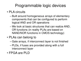
Programmable Logic Devices. Dense array of. Dense array of. AND gates. Product. OR gates. terms. Prgrammable Logic Organization. Pre-fabricated building block of many AND/OR gates (or NOR, NAND) "Personalized" by making or breaking connections among the gates. Inputs. Outputs.

E N D
Dense array of Dense array of AND gates Product OR gates terms Prgrammable Logic Organization • Pre-fabricated building block of many AND/OR gates (or NOR, NAND) • "Personalized" by making or breaking connections among the gates Inputs Outputs Programmable Array Block Diagram for Sum of Products Form
ORGANIZATION PAL PROM PLA AND ARRAY PROG. FIXED PROG. OR ARRAY FIXED PROG. PROG. Basic Programmable Logic Organizations • Depending on which of the AND/OR logic arrays is programmable, we have three basic organizations
F0 = A + B C F1 = A C + A B F2 = B C + A B F3 = B C + A Product Inputs Outputs t erm F F F F A B C 0 1 2 3 0 1 1 0 A B 1 1 - Reuse 0 0 0 1 B C - 0 1 of 0 1 0 0 A C 1 - 0 t erms 1 0 1 0 B C - 0 0 1 0 0 1 A 1 - - PLA Logic Implementation Key to Success: Shared Product Terms Equations Example: Personality Matrix Input Side: 1 = asserted in term 0 = negated in term - = does not participate Output Side: 1 = term connected to output 0 = no connection to output
B C A F3 F0 F2 F1 PLA Logic Implementation Example Continued - Unprogrammed device All possible connections are available before programming
B C A AB BC AC BC A F3 F0 F2 F1 PLA Logic Implementation Example Continued - Programmed part Unwanted connections are "blown" Note: some array structures work by making connections rather than breaking them
A B C D AB AB Notation for implementing F0 = A B + A B F1 = C D + C D CD CD CD+CD AB+AB PLA Logic Implementation Unprogrammed device Alternative representation Short-hand notation so we don't have to draw all the wires! X at junction indicates a connection Programmed device
A C B ABC A B C A B C ABC ABC ABC ABC ABC ABC ABC F1 F2 F3 F4 F5 F6 PLA Logic Implementation Design Example Multiple functions of A, B, C F1 = A B C F2 = A + B + C F3 = A B C F4 = A + B + C F5 = A B C F6 = A B C
PALs and PLAs What is difference between Programmable Array Logic (PAL) and Programmable Logic Array (PLA)? PAL concept — implemented by Monolithic Memories AND array is programmable, OR array is fixed at fabrication A given column of the OR array has access to only a subset of the possible product terms PLA concept — Both AND and OR arrays are programmable
PALs and PLAs • Of the two organizations the PLA is the most flexible • One PLA can implement a huge range of logic functions • BUT many pins; large package, higher cost • PALs are more restricted / you trade number of OR terms vs number of outputs • Many device variations needed • Each device is cheaper than a PLA
A B C D W X Y Z A A AB AB 0 0 0 0 0 0 0 0 00 01 11 10 00 01 11 10 0 0 0 1 0 0 0 1 CD CD 0 0 1 0 0 0 1 1 00 0 0 X 1 00 0 1 X 0 0 0 1 1 0 0 1 0 0 1 0 0 0 1 1 0 01 0 1 X 1 01 0 1 X 0 0 1 0 1 1 1 1 0 D D 0 1 1 0 1 0 1 0 0 1 X X 0 0 X X 11 11 0 1 1 1 1 0 1 1 C C 1 0 0 0 1 0 0 1 10 10 1 0 0 1 1 0 0 0 0 1 X X 0 0 X X 1 0 1 0 X X X X 1 0 1 1 X X X X B B 1 1 0 0 X X X X K-map for W K-map for X 1 1 0 1 X X X X 1 1 1 0 X X X X A A 1 1 1 1 X X X X AB AB 00 01 11 10 00 01 11 10 CD CD 00 0 1 X 0 00 0 0 X 1 X 01 01 0 1 0 0 X 0 1 D D 1 1 X X 0 1 X X 11 11 C C W = A + B D + B C X = B C Y = B + C Z = A B C D + B C D + A D + B C D 10 10 1 1 X X 1 0 X X B B K-map for Y K-map for Z PAL Logic Implementation Design Example: BCD to Gray Code Converter K-maps Truth Table Minimized Functions:
A B C D A BD BC 0 BC W = A + B D + B C X = B C Y = B + C Z = A B C D + B C D + A D + B C D 0 0 0 B C 0 0 A B C D BCD AD BCD W X Y Z PAL Logic Implementation Programmed PAL: Minimized Functions: 4 product terms per each OR gate
A A A 1 B 4 C B D 2 3 W D B 3 C B 2 D C 4 Z D 1 D 5 A B 2 X 1 B 1 C 3 C D C 1: 7404 hex inverters 2 Y B 1 B 2,5: 7400 quad 2-input NAND 3: 7410 t ri 3-input NAND 4: 7420 dual 4-input NAND PAL Logic Implementation Code Converter Discrete Gate Implementation 4 SSI Packages vs. 1 PLA/PAL Package!
A B C D A A AB AB ABCD 00 01 11 10 00 01 11 10 CD CD 00 00 1 0 0 0 0 1 1 1 ABCD 01 01 0 1 0 0 1 0 1 1 ABCD D D ABCD 11 11 0 0 1 0 1 1 0 1 C C 10 10 0 0 0 1 1 1 1 0 AC AC B B K-map for EQ K-map for NE BD A A BD AB AB 00 01 11 10 00 01 11 10 CD CD ABD 00 00 0 0 0 0 0 1 1 1 BCD 1 0 0 0 0 0 1 1 01 01 ABC D D 11 1 1 0 1 11 0 0 0 0 BCD C C 10 1 1 0 0 10 0 0 1 0 B B K-map for L T K-map for GT EQ NE LT GT PLA Logic Implementation Another Example: Magnitude Comparator
CLK Q0 Seq N Q1 Seq D D D D Q Q Q Open Com Reset Another Variation: Synchronous vs. Asynchronous Outputs
Complex Programmable Logic Devices • Complex PLDs typically combine PAL combinational logic with FFs • Organized into logic blocks • Fixed OR array size • Combinational or registered output • Some pins are inputs only • Usually enough logic for simple counters, state machines, decoders, etc. • e.g. GAL22V10, GAL16V8, etc.
GAL CPLD OLMC (Output Logic MacroCell) has OR, FF, output multiplexer and I/O control logic. Note that OLMC output is fed back to input matrix for use in other OLMCs.
PAL22V10 OLMC Configuration Modes • Registered Mode: active (low, high): Q’ is feedback as input only, no dedicated input in this mode • Combinational Mode: active (low, high) can feedback comb. Output (high, low) and/or dedicated input
OE CLK T S M U X 11 10 01 00 vcc AC0 AC1(n) P T M U X O 1 O M U X O 1 I/O(n) Q FROM AND ARRAY D Q XOR(n) F M U X 10- 11- 0-1 0-0 FEEDBACK FROM ADJ. STAGE OUTPUT(m) ACO AC1(m) AC1(n) CLK OE GAL16V8 OLMC Structure
PAL16V8 OLMC Configuration Modes Simple mode (combinational output) combinational output combinational output with feedback dedicated input Complex mode combinational output, with feedback combinational input from another OLMC Registered mode: active (low, high): Q’ is feedback as input (no dedicated input)
Field Programmable Gate Arrays (FPGAs) • FPGAs have much more logic than CPLDs • 2K to >10M equivalent gates • Requires different architecture • FPGAs can be RAM-based or Flash-based • RAM FPGAs must be programmed at power-on • External memory needed for programming data • May be dynamically reconfigured • Flash FPGAs store program data in non-volatile memory • Reprogramming is more difficult • Holds configuration when power is off
FPGA Structure • Typical organization in 2-D array • Configurable logic blocks (CLBs) contain functional logic (could be similar to PAL22V10) • Combinational functions plus FFs • Complexity varies by device • CLB interconnect is either local or long line • CLBs have connections to local neighbors • Horizontal and vertical channels use for long distance • Channel intersections have switch matrix • IOBs (I/O logic Blocks) connect to pins • Usually have some additional C.L./FF in block
Field-Programmable Gate Arrays structure • Logic blocks • To implement combinationaland sequential logic • Interconnect • Wires to connect inputs andoutputs to logic blocks • I/O blocks • Special logic blocks at periphery of device forexternal connections • Key questions: • How to make logic blocks programmable? • How to connect the wires? • After the chip has been fabbed • HW problems: 7-19, 7-20, 7-22, 7-23, 7-26 due 22/9/07