Download
1 / 27
280 likes | 290 Views
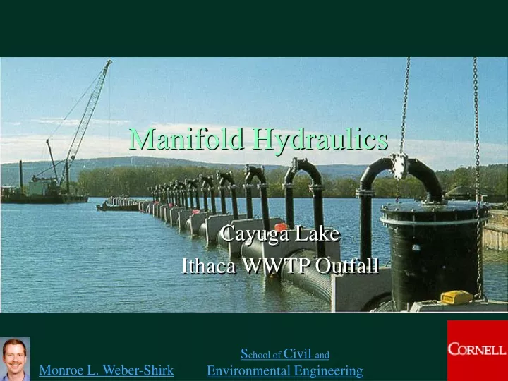
Manifold Hydraulics. Cayuga Lake Ithaca WWTP Outfall. Manifolds. Examples Sprinkler and drip irrigation systems wastewater discharge (multiport diffuser) Design objectives distribute a given discharge through multiple ports

E N D
Manifold Hydraulics Cayuga Lake Ithaca WWTP Outfall
Manifolds • Examples • Sprinkler and drip irrigation systems • wastewater discharge (multiport diffuser) • Design objectives • distribute a given discharge through multiple ports • choose pipe size given constraints of head loss, flow distribution, and cost uniformly
Objectives Minimize detrimental effects of the discharge on the environment Maximize initial Meet regulatory requirements Pollutants treated wastewater Cooling water from power plant Sites Rivers, Lakes, Oceans Multiport Diffuser BOD, N, P, metals dilution Heat
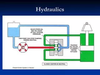
Multiport Diffuser energy grade line Remember Expansions hydraulic grade line ? z = 0 Representation of EGL and HGL for multiport diffuser. Does it make sense? What happens to HGL across the ports?
HGL Multiport Diffuser:Flow Calculations • We will derive equations in terms of ________ because pressure controls the port flow • Port flow • based on ______ equation • head loss through port (possibly including a riser) • Piezometric head change (H) across port • flow expansion • Piezometric head change ( H) between ports • Darcy-Weisbach and Swamee-Jain energy In diffuser
Port types • Nozzle riser • diffuser can be buried • nozzle can give direction to discharge • Port cast in wall of diffuser pipe • can’t be used if diffuser pipe is buried • generally not recommended
The Problem • Given a desired discharge • Calculate the head (pressure) required • Calculate the flow from each port • Develop a strategy to solve this problem • Simple Solution • ________ ________ in the diffuser pipe • Each port is an ________________ • Complete Solution • Determine HGL for the diffuser pipe Constant pressure exit (minor losses)
Strategy • The diffuser has many ports. If we can develop equations describing pressures and flows at one port we can then apply them to all of the ports. • We need equations describing • Flow from a port as a function of pressure (HGL) in the diffuser • Head loss (and pressure drop) in the diffuser • Flow in the diffuser _________________ (mass conservation)
Redo this w/ cs1 at entrance Port Flow z = 0 at water surface port piezometric head riser 0 Control volume? diffuser pipe
Riser Head Loss continuity
Riser Head Loss Coefficient (riser loss coefficient) Note that the riser coefficient is a function of ________ number. Reynolds Port velocity (or flow) given piezometric head in diffuser and a riser loss coefficient Orifice equation!
Flow ____________ Same equation applies as derived previously The velocities upstream and downstream from the port are determined from continuity Head Loss across Port expansion separation Vi Vi+1 2 1 Pressure Momentum _________ applied over entire cross section ___________ transferred over smaller area
Head loss occurs between section 1 and section 2 some distance downstream (~5 times the diameter of the diffuser) We will treat this head loss as if it all occurred immediately after the port Although there is head loss past the port the pressure (HGL) will __________ (proof coming up) HGL in Diffuser across Port EGL HGL DH from pressure recovery Vi Vi+1 increase 2 1
HGL in Diffuser across Port energy ________ equation using definition of piezometric head pressure increase across abrupt expansion
HGL in Diffuser across Port How can we find velocity downstream of port i? ___________ continuity Now we have the velocity downstream of the next port And we can calculate the increase in HGL across the port
HGL between Ports • HGL is parallel to EGL so H = E between diffusers • E = -hf and is due to friction loss (major losses)
Multiport Diffuser: Solution • The diffuser number, spacing, and jet velocity would be determined in part by the mixing required in the ambient water (Environmental Fluid Mechanics) • Available head and total flow would be determined by the water source hydraulics • A criteria may also be established for uniformity of flow from the ports • Alternate design criteria may dictate different solution methods
Multiport Diffuser: Solution • Given total discharge, pipe diameter, port size... • Calculate the piezometric head (measured from the water surface) required to give the necessary discharge in the first port • loss coefficient for port • head required to get desired flow from port
Multiport Diffuser: Solution • Starting with the first port and proceeding to the last port ... • Calculate the discharge from port i • Calculate velocity change in diffuser past port i • Calculate the piezometric head increase across port i • Calculate the piezometric head decrease between ports i and i+1 • Calculate the piezometric head at port i+1
Multiport Diffuser: Solution 4 HGL 1 decrease (_________ in pressure) 3 increase (__________ in pressure) 2 Vi 5 Known from previous step
Multiport Diffuser: Solution • Calculate the total discharge from the ports • Compare with design discharge • Adjust the _________ ____ at first port to give design discharge (use goal seeking, solver, or trial and error on spreadsheet). Alternately, set velocity past last port = 0 by changing piezometric head at first port. • It may be necessary to adjust diffuser or port diameter. • It will likely be possible to decrease the size of the diffuser pipe as the flow decreases. This may also help increase the discharge uniformity of the ports. piezometric head
Design Guidelines ~3 m/s • The port discharge velocity should be _______ to achieve good mixing with the ambient water. • The sum of all port areas must be less than the diffuser pipe area. The best area ratio (port area/diffuser area) is usually between 1/3 and 2/3. • The effects of pipe friction and pressure recovery will tend to cancel when • Ld is the total length of the diffuser pipe and the friction factor, f, is obtained by iteration since it is a function of the pipe diameter. • If the diffuser area obtained using this method is less than 1.5 x port area then this design criteria can not be used.
Multiport Diffuser:Thought Experiments • What happens to the uniformity of flow rates from the ports as the size of the diffuser pipe decreases? (Assume the pressure in the feeder pipe is varied to maintain constant flow while the port size remains the same.) ______________ • What happens to the uniformity of flow rates from the ports as the size of the ports decreases? ______________ • If the goal is uniform flow distribution why not use very small ports? ____________________ • Which port will have the highest flow rate? _____________ Less Uniform More Uniform Energy requirements First or last!
Diffuser Homework 20 ports Hometown WWTP 300 m 95 m
Quiz • The friction factor for major losses in pipe flow is relatively constant for a given geometry at high Reynolds numbers. Head loss is proportional to the friction factor. Therefore head loss is independent of Reynolds number at high Reynolds numbers. Explain why this is or isn’t true. • In large multiport diffusers the diameter of the main diffuser pipe is decreased in increments as the flow decreases (due to discharge from the ports). If you compare discharge from a port upstream from a decrease in diffuser pipe diameter with the port just downstream from a diameter change which port will have the highest flow? You may assume the transition in diffuser pipe diameter is smooth. Explain your answer.