Download
1 / 16
160 likes | 430 Views
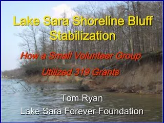
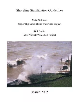
Shoreline Stabilization Guidelines. Mike Williams Upper Big Sioux River Watershed Project. Rick Smith Lake Poinsett Watershed Project. March 2002.

E N D
Shoreline Stabilization Guidelines Mike Williams Upper Big Sioux River Watershed Project Rick Smith Lake Poinsett Watershed Project March 2002
Most lakes experience shoreline erosion when increased water levels cannot be controlled. This will result in erosion above the scarp or even into the upland till. To prevent this from happening many landowners want to provide protection in the scarp area and above. The following are some helpful hints for the landowners that want to stop erosion of their property and protect the water quality of the receiving waters. 1
Water Quality Effects from Shoreline Erosion • Biologic Damage/Nutrient Loading: • Eroding shorelines carry nutrients and phosphorus into the water, providing food for algae growth. One pound of phosphorus grows 500 lbs. of algae. Blue-green algae is extremely toxic and can limit drinking water alternatives. • The suspended solids prevent light penetration needed for plant growth. Macrophytes are needed for fish reproduction. • Bacteria from animal waste and septic systems wash into the lakes, preventing immersion recreation and drinking water alternatives. • Residential areas are prone to high levels of lawn nutrients and herbicides • Physical Damage • Covers necessary sand/gravel/rock spawning areas permanently • Settling of sediment during spawning smothers fish eggs What conditions cause shoreline erosion? 1. Excessive water--usually attributed to heavy precipitation winters when snow melts on frozen ground and cannot be absorbed into soil. Snow that is not evenly distributed on land surface due to insufficient standing residue causes excessive accumulations in localized areas and overwhelms soil/water capacities. Both of these scenarios accompanied by possible spring rains result in heavy runoff of a short duration. 2. Winds--when wind conditions combine with elevated water levels, the force of the wave action is increased and reaches higher levels on the shoreline. This action is known as wave run-up. 3. Lack of protective surface--the greater the distance that wind has to react with water before it reaches shore (fetch), the higher the waves and the stronger the protective surface must be to resist erosion. 2
How does shoreline erosion occur? 1. Excessive water, wind or lack of protection must exist. 2. Soil becomes saturated and fluid. 3. Wave action pulls suspended solids from the shoreline to lower levels. 4. As new soil is exposed, the process continues. 5. Areas where water only flows over the shoreline, it erodes relatively slowly. Areas where the water undercuts the shoreline erode faster. When does shoreline erosion stop naturally...? When the slope of the shoreline achieves an 8:1 or 10:1 (horizontal vs. vertical) ratio, very little erosion will occur no matter what the protective surface. 3
Elements for Evaluation of stabilization type 1. Type of shoreline use--if the area is used by children and/or for swimming, rock is usually avoided and fractured rock or wire cage baskets (gabions) are undesirable. 2. Existing shoreline materials--sand beaches lend themselves better to walls. Rocked shorelines are better suited to remain rock if an adequate slope can be obtained. 3. Height needed for protection--when evaluating the highest level to which protection should reach, determine the highest historical flood levels and then add the amount of wave run up from calculations. Example: Lake Poinsett Ordinary High Water (OHW) level is 1651.5. Flood levels have reached 1656.0 on several occasions. Wave run up on most of the lake is calculated at 3.5 feet; therefore, the flood level plus run up equals 1659.5; the height of protection needed is 8 feet above OHW. 4. Site access--may determine the type of material to be used. If the water is deep immediately offshore and the bank is steep and/or high, it may be impossible to use any of these practices under current conditions. If water is shallow some distance from the shore, wave run-up will be less. 5. Any fill activities (not recommended) below the OHW mark will require a permit from the US Army Corps of Engineers. The application forms can be obtained from the COE or local Natural Resources Conservation Service offices. Check all appropriate zoning regulations that may require permits. 4
Wave Action Waves are measured from the bottom of the trough to the tip of the crest. The waves are as deep as they are tall compared to the still water level. However, this can be complicated by what is known as wind setup. During times of short-term storm events the water will rise on the side the wind is blowing into. A three-mile fetch (distance the wave travels) can mean greater than a 6-inch rise in the still water level. This must be added into the formula when designing the revetment. Run-up at Wind Speed 50 MPH Fetch Wave Height Run-up 3:1 Slope 4:1 Slope 1 mile 2.2 feet 4.18 3.3 2 miles 3.2 6.08 4.8 3 miles 3.9 7.41 5.85 4 miles 4.4 8.36 6.6 5 miles 4.7 8.93 7.05 Slope Height in Feet (Wave Height + Wind Set-up) Slope Length in Feet (run-up x slope) 4.18 + .42 = 4.60 3.3 + .42 = 3.72 6.08 + .60 = 6.68 4.8 + .60 = 5.40 7.41 + .75 = 8.16 5.85 + .75 = 6.60 8.36 + .82 = 9.18 6.60 + .82 = 7.42 8.93 + .93 = 9.86 7.05 + .93 = 7.98 4.60 x 3:1 = 13.80 3.72 x 4:1 = 14.88 6.68 x 3:1 = 20.04 5.40 x 4:1 = 21.60 8.16 x 3:1 = 24.48 6.60 x 4:1 = 26.40 9.18 x 3:1 = 27.54 7.42 x 4:1 = 29.68 9.86 x 3:1 = 30.57 7.98 x 4:1 = 31.92 Terrene Institute, 1993 Wave energy is proportional to the size of the wave height. As waves travel across the open water (fetch) they catch up to one another and create a monster wave greater than either of the original two. Therefore, many of the waves from a 2-mile fetch with a 50 MPH wind will be 3.2 feet high. When that wave reaches shore it will run up the shoreline or riprap until all the energy is dissipated. A 50 MPH wind at a 2 mile fetch will cause the wave to run up 6.08 feet on a 3:1 slope. By flattening the slope to a 4:1, the wave run-up would only be 4.8 feet. The same wave travelling 5 miles would be 4.7 feet high at the shore and would run up 9.12 feet at a 3:1 slope and 7.2 feet at a 4:1 slope. The vertical height of the revetment should be at least as high as the run-up plus the wind set-up. 5
Example: 50 MPH wind, 2 mile fetch, .45 foot wind set up, on a 3:1 slope would require a vertical height of 6.53 feet and a slope length of 19.59 feet or 5.25 feet high and 21.0 feet long on a 4:1 slope. The bank configuration will determine what slope you would use. Use the flattest slope conditions will allow. Ice Action Ice is a major concern when constructing shoreline protection devises. Ice expansion alone can exert 10-12 tons per square foot on anything in its way. If flooding occurs while the ice is still thick, strong winds can slam the ice ashore with a tremendous force. If the lake levels are above normal during freeze-up, sand and rocks captured in the ice can be lost to the lake during the spring. Every effort must be made to allow the ice to slide up and over the revetment instead of plowing into it. Be certain that the structure does not interfere with the longshore drift or you may change the shoreline of your neighbors. This drift could also undermine your toe and cause revetment failure if it is not placed properly. Rock revetments require some annual maintenance replacing rocks moved by the waves or ice, but seldom does the whole structure fail 6
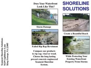
What practices can be used to stop erosion? Rock Rip Rap Sheet Pile Wall Concrete Wall 7
Rock Revetments The most common type of shoreline protection is rock riprap. It generally is the least expensive and easiest to repair. Rock provides the most natural look and temporary lake access structures can be placed on top of the rocks in the spring and removed in the fall. Annual rock replacement may be needed if ice or waves move a few of the rocks, but seldom is the complete structure damaged. Rock riprap has four components: the slope angle, the length of the slope, the toe and the filter fabric. Large lakes require about an 18-degree slope to the riprap protection. This would also be referred to as a 3:1 slope (3 feet horizontal for every 1 foot vertical drop). Small lakes that have small waves may get by on a 2:1 slope. The reason for the slope length at 18 degrees is directly related to wave run-up and could require a 4:1 slope or greater. Bulkheads There are three basic types of bulkheads: sheet piling, supported wood bank retainers and concrete seawalls. The most appropriate uses for bulkheads are for toe protection of eroding bluffs that are subject to erosive forces during periods of extremely high water. Bulkheads have two major drawbacks. The first is the high cost of the structure and the second is that they are doomed to massive failure from the forces of nature. The major points in favor of these structures are that they have very little maintenance after installation until the catastrophe happens, and they can be quite attractive. Experience has shown that placing an overtopping apron of fabric, decorative stone or sidewalk will protect the lawn from high water wave action. Sheet Pilebulkheads are driven into the shoreline one foot for every foot exposed. This could vary from site to site depending on the longshore drift. Locate the bulkhead on the scarp (see shoreline erosion drawing) to prevent the loss of the beach and additional shoreline erosion beyond the ends of the bulkhead. Wood bulkheads are used but not recommended. Toxins leach out from the treated wood and are not recommended for lakes that serve as drinking water sources. When damage does occur floating battering rams escape to pound the neighbor’s shore and serve as hazards for boating traffic. Wood bulkheads should be used only in harbors or areas not prone to large waves or ice flows. The major advantage to this type of bulkhead is that it is a little less expensive than others are at the outset. Concrete bulkheads are very attractive and can be built to divert ice movements. A slanted face on the wall will encourage ice to curve upwards as it expands on the shore. Installation costs can be high because of steep banks that need to be protected. Concrete can be expensive to repair and once damaged, requires annual repairs. Access to the shore and water can be built into these structures, which makes them popular. They normally have about a twenty-year life expectancy. 8
Components and Requirements of Rock Rip Rap 1. Toe trench--the purpose of a toe trench is to prevent water from undermining the protected area and to protect the structure from damage from ice heaves and wind-driven ice sheets. The toe trench should be approximately 3 feet deep and filled with a single layer of 3 1/2- to 4-foot diameter rock. Whatever the size, 2/3rds of the rock should be buried for stability during ice movement. 9
2. Bank Slope Preparation--3:1 or flatter back slope to minimize the force of the waves. Steeper slopes will cause rock to tumble down the slope during high water periods. The sloped backfill needs to have the rock removed and the material graded and compacted. 3. Fabric--A minimum of 6-8 oz. of Geotextile fabric is the protection barrier. All the other components of the design are to keep the fabric in place to do the work. Fabric allows water to move freely through it but not the solids, thus protecting the integrity of the shoreline. Fabric will underlie the toe trench and cover the entire back slope. Any edges of fabric should be overlapped by 2 feet and no fabric should be left uncovered as it deteriorates in sunlight. 4. Rock covering--the purpose of the rock is to hold the fabric in place and prevent ice damage. A single layer of 14” to 20” diameter rock placed as near to solid as possible is recommended for most lakes subject to erosion. The second layer of rock should be the type to fill the voids of the first layer and provide a relatively even surface. 10
Components of a Fabricated Sheet Pile Wall 1. Steel Sheet Pile--interlocks with adjoining sheets of various lengths but ten-foot length and quarter- inch thickness are the most common. 2. Deadman- a system of ten-foot, one-inch diameter rods connecting the wall to a completely buried sheet of steel prevents the wall from tipping out. 11
3. Fill behind the wall- cannot contain large rock and compaction is necessary before first year freeze up. If the wall gets water from the land side, a backfill immediately next to the wall of small aggregate is needed along with additional weep holes to provide drainage.Solid, tamped backfill is a must. 4. Placement of wall-the base of the wall will be placed above the OHW to prevent freezing to the ice mass. (Lake Poinsett requires at least 2 feet above). At least half of the sheet will be buried for stability. If more than 6 feet of wall is exposed, a second tier of deadman rods is recommended so that no more than 3 feet of vertical wall is unanchored. 12
Components of a Concrete Wall 1. A 15” x 8’ footing is poured at water level or ground level to keep ice from hooking the wall. It should be reinforced with rebar on a 12” center. Vertical rebar should be inserted into the foot while soft, on a 12” center, five feet tall above the footing. 2. The front wall should be 4’ tall, sloped from 20” at the base to 6” at the top. The back wall should be vertical. 13
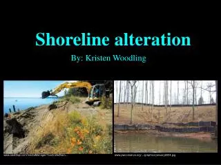
3. Every sixteen feet, build an 8” reinforcement panel at right angles to the wall. 4. We suggest placing drain tile at the bottom of the back wall. Cover with 3/4” inch rock and pea gravel before backfilling. Provide weep holes for water loss. Concrete wall during construction, before the backfill is done. This picture shows the ‘strongback’ supports of the concrete. Visible on the lower left is a protective wing to prevent end cutting. Work is being done at high water level to regain lost terrain. This project was completed at 18” above OHW. Patio and sidewalk that serve as protection from overtopping by high waves. Waves can get behind the wall and eat it out. Note how the backfill went in and how the landowner saved the trees. 14
Shoreline Stabilizing Structures- Must be placed at or below the gradient slope of natural erosion, which is between 8:1 and 10:1 depending on soil characteristics. Failure to place structures deep enough will allow undercutting. 15