Download
1 / 29
330 likes | 643 Views
Semiconductor Device Physics. Lecture 8 PN Junction Diodes: I-V Characteristics Dr. Gaurav Trivedi , EEE Department, IIT Guwahati. Dominant breakdown mechanism is tunneling. Empirical Observations of V BR. V BR decreases with increasing N,. V BR decreases with decreasing E G .

E N D
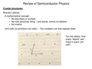
Semiconductor Device Physics Lecture 8 PN Junction Diodes: I-V Characteristics Dr. GauravTrivedi, EEE Department, IIT Guwahati
Dominant breakdown mechanism is tunneling Empirical Observations of VBR • VBR decreases with increasing N, • VBR decreases with decreasing EG. • VBR : breakdown voltage
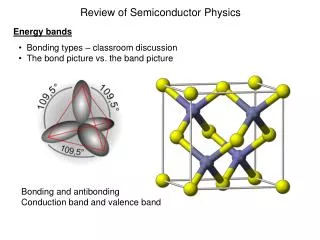
Charge Control Approach • Integrating over the n quasineutral region (after all terms multiplied byAdx), QP QP • Furthermore, in a p+n junction, 0 • So: In steady state
Charge Control Approach • In steady state, we can calculate pn junction current in two ways: • From slopes of Δnp(–xp) and Δpn(xn) • From steady-state charges QN and QP stored in each “excess minority charge distribution” • Therefore, • Similarly,
Charge Control Approach • Moreover, in a p+n junction: In steady state
Narrow-Base Diode • Narrow-base diode: a diode where the width of the quasineutral region on the lightly doped side of the junction is on the order of or less than one diffusion length. n-side contact
Narrow-Base Diode I–V • We have the following boundary conditions: • Then, the solution is of the form: • Applying the boundary conditions, we have:
Narrow-Base Diode I–V • Solving for A1 and A2, and substituting back: • Note that • The solution can be written more compactly as
Narrow-Base Diode I–V • With decrease base width, xc’0: • Δpn is a linear function of x due to negligible thermal R–G in region much shorter than one diffusion length • JPis constant • This approximation can be derived using Taylor series approximation
Narrow-Base Diode I–V • Because , then • Then, for a p+n junction:
Narrow-Base Diode I–V • If xc’ << LP, • Resulting • Increase of reverse bias means • Increase of reverse current • Increase of depletion width • Decrease of quasineutral region xc’=xc–xn
Wide-Base Diode • Rewriting the general solution for carrier excess, • For the case of wide-base diode (xc’>> LP), Back to ideal diode solution
Wide-Base Diode • Rewriting the general solution for diffusion current, • For the case of wide-base diode (xc’>> LP), Back to ideal diode solution
Small-Signal Diode Biasing • When reversed-biased, a pn junction diode becomes functionally equivalent to a capacitor, whose capacitance decreases as the reverse bias increases. • Biasing additional a.c. signal va can be viewed as a small oscillation of the depletion width about the steady state value. V0 << VA RS : serial resistance C : capacitance G : conductance Y : admittance
Total pnJunction Capacitance Junction / depletion capacitance, due to variation of depletion charges Minority carrier lifetime Diffusion capacitance, due to variation of stored minority charges in the quasineutral regions • CJ dominates at low forward biases, reverse biases. • CD dominates at moderate to high forward biases.
Relation Between CJ and VA • For asymmetrical step junction, NB : bulk semiconductor doping, NA or ND as appropriate. • Therefore,