Download
1 / 44
450 likes | 585 Views
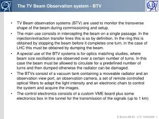
Observation of beam halo with corona graph. Magnifier lens. Objective lens. Opaque disk to block glare of central image. 1. Diffraction fringes vs. beam tail (halo). Observation with normal telescope.

E N D
Magnifier lens Objective lens Opaque disk to block glare of central image 1. Diffraction fringes vs. beam tail (halo) Observation with normal telescope
Diffraction fringes makes tail surrounding from the central beam image.Intensity of diffraction tail is in the range of 10-2 -10-3 of the peak intensity.The diffraction tail disturb an observation of week object surrounding from bright central beam
Convolution between diffraction fringes and beam profile Diffraction fringes Gaussian beam profile
Convolution between diffraction fringes and beam profile Diffraction fringes Gaussian beam profile Blocked by opaque disk
2.The coronagraph to observe sun coronaDeveloped by B.F.Lyot in 1934 for a observation of sun corona by artificial eclipse.Special telescope having a re-diffraction system to eliminate a diffraction fringe.
Anti-reflection disk Field lens Relay lens Baffle plate (Lyot stop) Objective lens Opaque disk Baffle plates to reduce reflection Optical system of Lyot’s corona graph
3. Re-diffraction optics system to eliminate the diffraction fringe
Opaque disk Field lens Lyot stop Objective lens Re-diffraction optics system Re-diffraction optical system Opaque disk
Opaque disk Function of the field lens : make a image of objective lens aperture onto Lyot stop Field lens Lyot stop Objective lens Re-diffraction optics system Re-diffraction optical system Opaque disk
Opaque disk Function of the field lens : make a image of objective lens aperture onto Lyot stop Blocking diffraction fringe by Field lens Lyot stop Objective lens Re-diffraction optics system Re-diffraction optical system Opaque disk
4. Photographs of coronagraph Front view of the coronagraph
Objective lens with anti-reflection disk to block reflected light from opaque disk
View from the back side Field lens Lyot’s stop
Zoom up of opaque disk. Shape is cone and top-angle is 45º
5. Background sources • Scattering by defects on the lens surface (inside) such as scratches and digs. • 2. Scattering from the optical components (mirrors) near by coronagraph. • 3. Reflections in inside wall of the coronagraph. Cover the inside wall with a flock paper (light trapping material). • 4. Scattering from dust in air. Use the coronagraph in clean room.
5-1.Scattering by defects on the lens surface such as scratches and digs. With normal optical polishing, for example S&D 60/40 scattered light intensity : about 10-3 times of input light intensity.
5mm S&D 60/40 surface of the glass
5mm Result of careful optical polishing for the objective lens
5-2. Scattering from the optical components (mirrors) near by coronagraph
Set up of SR monitor at the Photon factory electron beam orbit Scattering from Be-mirror is about 5x10⁻⁷ source point SR beam 2940 1100 mirror 2900 mirror coronagraph Scattering from the mirror which set at 2m in front of coronagraph is about6x10-5
Optical axis of surface reflection Low scattering noise mirror for optical path To escape from scattering noise from mirrors in the optical path, we used back-coated mirror with well polished optical flat having a small wedge angle. The wedge angle is necessary to separate surface reflection Optical axis reflected by back Al coating
6. Observation of beam tail (halo) at the Photon Factory, KEK
Intentionally spread some dust on the mirror in 2m front of the coronagraph
Diffraction tail observed without Lyot’s stop 30° Entrance pupil is intentionally rotated by 30º to recognize diffraction tail easily.
Move the opaque disk slightly to show the edge of central beam image (diamond ring!)
65.8mA 61.4mA 54.3mA 45.5mA 35.5mA 396.8mA Multi-bunch bunch current 1.42mA Beam tail images in the single bunch operation at the KEK PF measured at different current
Observation for the more out side Single bunch 65.8mA Exposure time of CCD : 3msec Intensity in here : 2.05x10⁻⁴ of peak intensity 2.55x10⁻⁶ Far tail Exposure time of CCD : 100msec Background leavel : about 6x10⁻⁷
RF bucket x 33 Strong tail in RF bucket Weak tail in outside of RF bucket
7. Conclusions • The coronagraph was designed and constructed for the observation of weak object (such as tail and halo) surrounding from central glare of the beam. • Optical polish of the objective lens is key point to realize good S/N ratio, and we reached ratio of background to peak intensity 6x10⁻⁷. • Spatial resolution is about 50mm • By using the coronagraph, we observe beam tail at the photon factory storage ring. As results; 1. a strong beam tail was observed in inside of RF bucket 2. a weak, and wide-spread tail is observed in outside of RF bucket.
LHC bend 7TeV 0.2A PF bend 2.5GeV 0.45A Visible SR
total s component p component
Visible SR at 7TeV is ten times stronger than PF! 1. Stationary and dynamical beam profile observation via normal focusing method with fast gated camera. 2. Beam size measurement via SR interferometer with the spatial resolution better than few mm. 3. Beam halo observation via coronagraph. 4. Temporal beam profile observation via streak camera.
Intensity distribution on Lyot’s stop by re-diffraction system is given by; In here, F(x) is disturvance of the light on field lens
x1 x2 The integrationperforms x1 and x1 x1: radius of field lens x2: radius of opaque disk
Diffraction tail Bam tail in s Comparison between beam tail and diffraction tail