Download

1 / 34

E N D
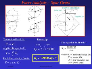
Forces on Reciprocating Parts • Piston Effort FP = FL ± FI ± WR RF • Net Load on Piston (single acting Cylinder) FL = p × A1 • Double acting Cylinder FL =p1 × A1 p2 × A2 • Inertia Force 𝐹I= 𝑚𝜔2𝑟[𝑐𝑜𝑠𝜃 + 𝑐𝑜𝑠2𝜃 /2𝑛] • Force acting along C.R 𝐹𝑄 = 𝐹𝑃 cos∅
Forces on Reciprocating Parts • Normal reaction 𝐹𝑁 = 𝐹𝑄𝑠𝑖𝑛∅ = 𝐹𝑃𝑡𝑎𝑛∅ • Crank pin effort 𝐹𝑇 = 𝐹𝑄sin (𝜃 + ∅) • Thrust on crankshaft 𝐹𝐵 = 𝐹𝑄 cos(𝜃 + ∅) • Crank effort 𝑇 = 𝐹𝑇 × 𝑟 = [ 𝐹𝑃 cos𝜃sin(𝜃 + ∅)] × 𝑟
Forces in engine • Piston effort FP • Force along connecting rod FQ • Thrust on cylinder walls FN • Thrust on crankshaft bearings FB • Crank-pin Effort/Tangential force FT
Forces in engine • Piston effortFP FL = Gas forces/Load = P1A1 – P2 (A1-A2) FI = Inertia forces = ma Rf= Friction forces WR = weight of piston
Forces in engine 2. Force along connecting rod FQ
Forces in engine 3.Thrust on cylinder walls FN
Forces in engine 4. Thrust on crankshaft bearings
Forces in engine 5.Crank pin effort 6. Turning Moment on crank shaft T = FT * r
Engine force analysis problems • Displacement of piston,x = • Velocity of piston, v = • Acceleration of piston, a = • Rel. Between q & f =>
Dynamic force analysis of reciprocating engine - Formulae 5. Piston effort, • Gas forces • Inertia forces • Frictional forces, RF = m .N
Dynamic force analysis of reciprocating engine - Formulae 6. Thrust on connecting Rod, 7. Thrust on cylinder walls, 8. Thrust on crank shaft bearings, 9. Crank – Pin effort 10. Torque , T = FT x r
Problems on Forces on Reciprocating Parts • The crank-pin circle radius of a horizontal engine is 300 mm. The mass of the reciprocating parts is 250 kg. When the crank has travelled 60° from I.D.C., the difference between the driving and the back pressures is 0.35 N/mm2. The connecting rod length between centres is 1.2 m and the cylinder bore is 0.5 m. If the engine runs at 250 r.p.m. and if the effect of piston rod diameter is neglected, calculate : 1. pressure on slide bars, 2. thrust in the connecting rod, 3. tangential force on the crank-pin, and 4. turning moment on the crank shaft
Given: r = 300 mm = 0.3 m ; mR = 250 kg; θ = 60°; p1 – p2 = 0.35 N/mm2; l =1.2 m ;D= 0.5 m = 500 mm ; N= 250 r.p.m. orω= 2π× 250/60 = 26.2 rad/sTo find :1. pressure on slide bars, 2. thrust in the connecting rod, 3. tangential force on the crank-pin, and 4. turning moment on the crank shaft Using Formulas • Net load on the piston =Fp=FL- (P1-P2)П/4*D2 • Ratio of length of Connecting rod and Crank n=l/r • Inertia Force 𝐹𝐼 = 𝑚𝜔2𝑟[𝑐𝑜𝑠𝜃 + 𝑐𝑜𝑠2𝜃 /2𝑛] • Piston Effort FP= FL ± FI • Pressure on slide bars sinφ =sinθ /n and FN =FP tanφ • Thrust in the connecting rod FQ=Fp/cos φ • Tangential force on the crank-pin FT= FQsin (θ+φ) • Turning moment on the crank shaft T=FT*r
Solution • First of all, let us find out the piston effort (FP). • We know that net load on the piston,
Pressure on slide bars Let φ = Angle of inclination of the connecting rod to the line of stroke. We know that, sinφ =sinθ /n= sin 60/4=0.866 /4= 0.2165 ∴ φ = 12.5° We know that pressure on the slide bars, FN=FPtanφ = 49.424 × tan 12.5° = 10.96 kN Ans.
Thrust in the connecting rod and Tangential force on the crank-pin We know that thrust in the connecting rod, FQ = FP/cosφ = 49.424/cos 12.5° =50.62 kNAns We know that tangential force on the crank pin, FT =FQsin (θ+φ) = 50.62 sin (60+12.5 ) = 48.28 kNAns
.Turning moment on the crank shaft • We know that turning moment on the crank shaft, T=FT *r =48.28* 0.3 =14.484 kN-m Ans
The crank-pin circle radius of a horizontal engine is 300 mm. The mass of thereciprocating parts is 250 kg. When the crank has travelled 60° from I.D.C., the difference between the driving and the backpressures is 0.35 N/mm2. The connecting rod length between centres is 1.2 m and the cylinder bore is 0.5 m. If the engine runs at 250 r.p.m. and if the effect of piston rod diameteris neglected, calculate :i. pressure on slide bars, ii. Thrust in the connecting rod, iii. Tangential force on the crank-pin, and iv turning moment on the crank shaft. Solution
To find; FN Thrust on side walls FQ Thrust on connecting rod FT Crank-pin effort/ Tang. force T, Torque Given:Crank radius r = 300 mm m = 250 kg; q = 60; p1 – p2 = 0.35 N/mm^2 ;l = 1.2m; Cylinder Bore, D = 0.5m = 500mm Speed in rpm, N = 250rpm
n = l/r = 1.2/0.3 = 4 • Gas forces,
3. Angle bet. Connecting rod and horizontal f 4. Pressure on slide bars/ Thrust on walls FN 5. Thrust in connecting rod FQ
6. Crank-Pin effort FT 7. Turning moment on crank shaft T
Vertical engine Top-Dead center Bottom-Dead center L
Problem on vertical engine A vertical petrol engine 100 mm diameter and 120 mm stroke has a connecting rod 250 mm long. The mass of the piston is 1.1 kg. The speed is 2000 r.p.m. On the expansion stroke with a crank 20° from top dead centre, the gas pressure is 700 kN/m2. Determine: • Net force on the piston • Resultantt load on the gudgeon pin, 3. Thrust on the cylinder walls, and 4. Speed above which, other things remaining same, the gudgeon pin load would be reversed in direction.
Given: • D = 100 mm = 0.1 m • L = 120 mm = 0.12 m or • r = L/2 = 0.06 m ; • l = 250 mm = 0.25 m ; • mR = 1.1 kg ; • N = 2000 r.p.m. Or • ω = 2 π × 2000/60 = 209.5 rad/s • q = 20°; • p = 700 kN/m2 To Find 1.Net force on the piston 2.Resultant load on the gudgeon pin, 3. Thrust on the cylinder walls, and 4. Speed above which, other things remaining same, the gudgeon pin load would be reversed in direction
Net force on piston • Gas Forces • Inertia Forces • Final piston effort
2. Resultantt load on the gudgeon pin,(connecting rod thrust) 3. Thrust on the cylinder walls,
4. Speed above which, the gudgeon pin load would be reversed in direction. • Gudgeon pin load i.e. FQ will be negative if FP is negative, And FP will be negative when FL and W are less than FI => FI >FL + W