Download
1 / 20
210 likes | 326 Views
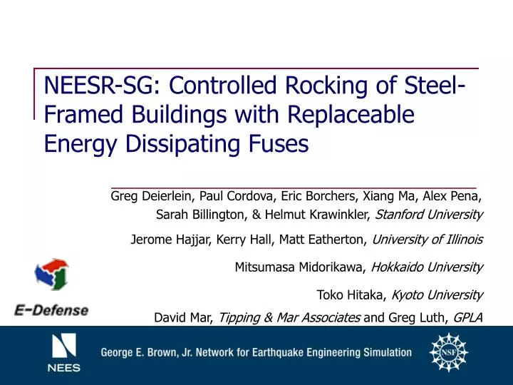
NEESR-SG: Controlled Rocking of Steel-Framed Buildings with Replaceable Energy Dissipating Fuses. Greg Deierlein, Paul Cordova, Eric Borchers, Xiang Ma, Alex Pena, Sarah Billington, & Helmut Krawinkler, Stanford University Jerome Hajjar, Kerry Hall, Matt Eatherton, University of Illinois

E N D
NEESR-SG: Controlled Rocking of Steel-Framed Buildings with Replaceable Energy Dissipating Fuses Greg Deierlein, Paul Cordova, Eric Borchers, Xiang Ma, Alex Pena, Sarah Billington, & Helmut Krawinkler, Stanford University Jerome Hajjar, Kerry Hall, Matt Eatherton, University of Illinois Mitsumasa Midorikawa, Hokkaido University Toko Hitaka, Kyoto University David Mar, Tipping & Mar Associates andGreg Luth, GPLA
Controlled Rocking System Component 3 – Replaceable energy dissipating fuses take majority of damage Component 2 – Post-tensioning strands bring frame back down during rocking Component 1 – Stiff braced frame, designed to remain essentially elastic - not tied down to the foundation. Bumper or Trough
Rocked Configuration • Corner of frame is allowed to uplift. • Fuses absorb seismic energy • Post-tensioning brings the structure back to center. Result is a building where the structural damage is concentrated in replaceable fuses with little or no residual drift
Pretension/Brace System Fuse System c b c d e b Base Shear a,f Base Shear Fuse Strength Eff. Fuse Stiffness a d PT Strength g Drift Frame Stiffness g f e Drift b c Origin-a – frame strain + small distortions in fuse a – frame lift off, elongation of PT b – fuse yield (+) c – load reversal (PT yields if continued) d – zero force in fuse e – fuse yield (-) f – frame contact f-g – frame relaxation g – strain energy left in frame and fuse, small residual displacement Base Shear 2x Fuse Strength d a PT Strength e f PT – Fuse Strength g Drift Combined System
Attributes of Fuse high initial stiffness large strain capacity energy dissipation Candidate Fuse Designs ductile fiber cementitious composites steel panels with slits low-yield steel mixed sandwich panels damping devices Shear Fuse Testing - Stanford Panel Size: 400 x 900 mm
Trial Steel Fuse Configurations thickness t h a L b B Butterfly Panel Rectangular Link Panel • Butterfly – b/a ratio • Out of plane bracing • KEY PARAMETERS: • Slit configuration • b/t and L/t ratios
ABAQUS Modeling of Fuse Similar Deformation Mode
Parametric Study – Parameters Studied • A/B ratio – geometry of frame • Overturning Ratio (OT) – ratio of resisting moment to design overturning moment. OT=1.0 corresponds to R=8.0, OT=1.5 means R=5.3 • Self-Centering Ratio (SC) – ratio of restoring moment to restoring resistance. • Initial P/T stress • Frame Stiffness • Fuse type including degradation
Sample of Parametric Study Results: Mean Values of Peaks from Time Histories OT=1.0 SC=1.0 A/B=2.3 SC=1.0 A/B=2.3 OT=1.0
UIUC Half Scale Tests Typical Alternative Configuration: Six Fuses
UIUC Half Scale Tests Column Base Elevation of Post Tensioning
System Test at E-Defense (2009) • Large (2/3 scale) frame assembly • Validation of dynamic response and simulation • Proof-of-Concept • construction details • re-centering behavior • fuse replacement • Collaboration & Payload Projects Special thanks to Profs. Takeuchi, Kasai, Nakashima and all those involved in the testbed development and E-Defense operations
Conclusion • Seismic loads prescribed in current building codes assume considerable inelasticity in the structure during a severe earthquake. This can result in structural damage and residual drift that cannot be economically repaired. • The controlled rocking system satisfies two key performance goals: • Minimize residual drift. • Concentrate bulk of structural damage in replaceable fuses. • Experimental and analytical work has been carried out at Stanford to optimize fuses. • A parametric study was conducted at UIUC to optimize A/B ratio, OT ratio, and SC ratio. • Half-scale tests will be conducted at the UIUC MUST-SIM Facility to improve details and validate the performance of the controlled rocking system for implementation in practice. • Tests will be carried out at E-Defense to further validate the system performance and demonstrate the self-centering and repairability of the controlled rocking system when subjected to a realistic ground motion.