Download
1 / 15
150 likes | 380 Views
Using Programmable Logic to Accelerate DSP Functions “An Overview“. Greg Goslin Digital Signal Processing Applications Manager Corporate Applications Group 15OCT95. Agenda. When to use FPGAs for DSP, an Overview What is Digital Signal Processing (DSP)? Where is DSP Used?

E N D
Using Programmable Logic to Accelerate DSP Functions“An Overview“ Greg GoslinDigital Signal Processing Applications Manager Corporate Applications Group15OCT95
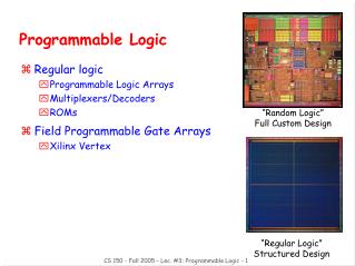
Agenda • When to use FPGAs for DSP, an Overview • What is Digital Signal Processing (DSP)? • Where is DSP Used? • Traditional DSP Approaches. • The Promise of Programmable Logic • Case Study: Finite Impulse Response Filter. • Case Study: Viterbi Decoder. • Building Fast Filters in FPGAs, a Tutorial • Efficient Algorithms for FPGAs. • Using Distributed Arithmetic for Filter Designs. • How to use an FPGA to Building Filter Designs. • Design Methodologies for DSP in FPGAs • Design Entry and Third Party Software Tools.
What is Digital Signal Processing (DSP)? • DSP is the arithmetic processing of digital signals sampled at regular intervals • DSP can be reduced to three trivial operations: • Delay • Add • Multiply • Accumulate = Add + Delay • MAC = Multiply + Accumulate • The MAC is the engine behind DSP • More MACs = Higher Performance, Better Signal Quality • MACs vs. MIPS, not always equal Filter 3 MACs 50* MACs 100 MACs
Where is DSP Used? DSP has many names and acronyms: • Filtering - • FIR • IIR • Viterbi • Compression - • Decompression • MPEG • JPEG • ADPCM • Convolution • Correlation • Modulation (Source: Forward Concepts)
Traditional DSP Approaches • Digital Signal Processor IC • Software programmable, like a microprocessor • Single MAC unit • All processing done sequentially • Fit the algorithm to the architecture • ASIC (gate array) • Fit the architecture to the algorithm • Significantly higher performance than DSP processor • High cost and high risk to develop • Usually only for high-volume applications ‘Traditional’ DSP Processor Analog input Analog output MAC Memory ADC DAC Digital output Data Controller
The Promise of Programmable Logic ASIC DSP Processor FPGA • Best from both worldsplus: • Efficient IC architecture • System features • Short design cycle • Automatic migration to low cost HardWire • Pros • High performance • High density • One chip solution • Cons • High design risk • Long design cycle • Pros • High flexibility • Good adaptability • Low design risk • Cons • Performance • Hardware Complexity
XC4000E Configurable Logic Blocks (CLBs)Simplified Block Diagram Look Up Tables can be defined as any 4-input function including 16x1 SRAM C1 C2 C3 C4 S/R control H1 DIN S/R EC G4 G3 G2 G1 DIN logic func. of G1 to G4 SD F' G' D YQ Q G' H' logic func. of F',G', and H1 M U X EC G' RD H' 1 F4 F3 F2 F1 GY M U X logic func. of F1 to F4 G' SD F' XQ D Q F' H' DIN EC RD H' 1 F' Muxes allow 3 independent inputs to “H” function generator S/R control K (clock) FX
XC4000E Dual-Port RAM Common ADDR_F Read/Write Address 4 DIN Bit_0 D Q D Q CE 0 Each CLB can be configured as 16x1 dual-port, synchronous SRAM Simultaneous read access through ADDR_F and ADDR_G Write address, data, and control are synchronized to write clock DOUT_F 0 MUX Bit_1 D Q WE 15 D Q CE DECODER 15 0 DOUT_G MUX MUX 15 Bit_15 D Q CE F G WCLK ADDR_G Read-Only 4 Address Synchronization Registers
DSP Functions Are Parallel Algorithms • 8-Bit, 16-Tap Finite Impulse Response (FIR) Filter • Equation: Symmetrical Coefficients
FPGAs Outperform‘Traditional’ DSP Processors 25 22.00 8-Bit, 16-Tap FIR Filter Parallel Distributed Arithmetic (est.) Performance Comparisons (PDA) (External Performance) 20 16.00 15 Performance Relative to 50 MHz Fixed-Point DSP FPGA 10 FPGA Serial Distributed Arithmetic (SDA) 4.00 5 2.60 1.00 MCM 0.24 FPGA 0 133 MHz Single XC4003E-3 Four XC4010E-3 XC4013E-2 Pentium™ 50 MHz FPGA 50 MHz FPGA FPGA Processor 750 KHz DSP 3 MHz (68% util.) 8 MHz DSPs 12 MHz (98% util.) 56 MHz (75% util.) 66 MHz
What to Look for in Your DSP Application • Identify Parallel Data Paths • Find Operations that Require Multiple Clock Cycles • Processor Bottlenecks DSP Processor ASIC FPGA Flexibility Parallel Data Paths Scaleable Bandwidth Design Modification Device Expansion = YES = NO
When to Use FPGAs for DSP • High sample rates • Up to 66 MHz with XC4000E-2 • Low sample rates • Integrate DSP + system logic in a low-cost DSP using serial sequential algorithm • Short word lengths • DA algorithm gets faster with shorter word length • Lots of filter taps • FPGA processes all taps in parallel, faster than DSP • Fast correlators • Single-chip solution required • HardWire gate array migration path for high-volume designs
Information on DSP Applications • Greg Goslin • Digital Signal and Image Processing Applications Manager • Email: dsp@xilinx.com • WEB: http://www.xilinx.com/dsp.htm • Fax: 408-879-4442