Download
1 / 39
390 likes | 851 Views
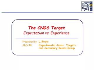
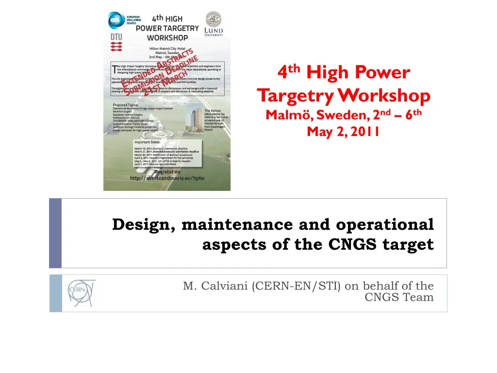
4 th High Power Targetry Workshop Malmö, Sweden, 2 nd – 6 th May 2, 2011. Design, maintenance and operational aspects of the CNGS target. M. Calviani (CERN-EN/STI) on behalf of the CNGS Team. Outline. Introduction to CNGS physics case and design guidelines CNGS target design

E N D
4th High Power Targetry Workshop Malmö, Sweden, 2nd – 6thMay 2, 2011 Design, maintenance and operational aspects of the CNGS target M. Calviani (CERN-EN/STI) on behalf of the CNGS Team
Outline • Introduction to CNGS physics case and design guidelines • CNGS target design • FLUKA simulation optimization • Engineering design of the target and auxiliary equipment • Operational aspects of the installation: selected topics • Maintenance of the target system • Investigation on target motorization failure MC - Design, maintenance and operational aspects of the CNGS target - 4th HPTW
General layout of the CNGS installation • Air cooled graphite target magazine (p/K production) • 2 horns (horn + reflector) water cooled, pulsed with 10ms half-sine wave of 150/180 kA, 0.3 Hz, remote polarity change (focusing of charged mesons) • Decay pipe 1000m 2.45 m Ø, 1 mbar vacuum (decay in flight) • Hadron absorber C core + Fe, ~100 kW absorption proton and other hadrons • 2 muon monitor stations: m fluxes and profiles (direction of the n beam towards LNGS) MC - Design, maintenance and operational aspects of the CNGS target - 4th HPTW
SPS: 2 fast extraction of 400 GeV/c protons every 6 seconds • Nominal 2x 2.4*1013pppin 10.5 ms interleaved by 50 ms(currently 2x 2.1*1013 ppp) • Beam power: ~500 kW (currently 448 kW) • Sigma = 0.53 mm • Ultimate 2x 3.5*1013ppp North Area and Prevessin site Target area SPS Decay pipe LHC CNGS TI8 LHC injection TI2 LHC injection Hadron stop + muon pits PS and Meyrin site n towards LNGS MC - Design, maintenance and operational aspects of the CNGS target - 4th HPTW
Physics requirement for the CNGS beam 3.5 GeV (threshold for t production) CNGS is a long base-line appearance experiment, designed for nmnt oscillation search nt appearance in a (almost) pure nm beam • The energy spectrum of the nm is well matched to R~stCC/En2 at ~17 GeV to maximize the signal rate (nt appearance) • Low anti-nm and ne contamination • CNGS approved for 22.5*1019 POT (5 y with 4.5*1019 POT/y) • … up to now 10.5*1019 POT • Few nt expected in OPERA and ICARUS detectors MC - Design, maintenance and operational aspects of the CNGS target - 4th HPTW
Example of neutrino events in OPERA and ICARUS • OPERA: 1.2 kton emulsion target detector • 146000 lead emulsion bricks First nt detected • ICARUS: 600 ton Liquid Argon TPC • High sensitivity and online reconstruction of tracks arXiv:1006.1623v1 8 June 2010 MC - Design, maintenance and operational aspects of the CNGS target - 4th HPTW
CNGS description with FLUKA The CNGS beam-line facility is fully described within the FLUKA Monte Carlo code for various purposes: Optimization of the target design in the initial project stages Energy deposition in the secondary beam line mechanical and thermal analysis Prompt and residual dose rate radioprotection Monitor beam response commissioning and diagnostics (mdistrib. at m-pits) Predict neutrino beam energy spectrum/composition at LNGS TSG4 TCC4 Decay pipe target horn He bags reflector MC - Design, maintenance and operational aspects of the CNGS target - 4th HPTW
Past experience at CERN The design of the CNGS target takes advantage of the experience with previous fixed targets at CERN • Operational experience with the target (e.g. corrosion in humid/radioactive environment) • FLUKA used for beam simulations and comparison with n-induced CC events in NOMAD T9 WANF target (CHORUS and NOMAD experiments) (~180 kW beam) 11 Be rods, 3 mm Ø, 10 cm long, spaced every 9 cm, He cooled (forced flow) • WANF muon pits good agreement for the 3 detector regions S. Peraire, 1996 MC - Design, maintenance and operational aspects of the CNGS target - 4th HPTW
Physics requirement of the CNGS target • Provide the highest possible proton interactions • Decrease probability of secondariesreinteraction • For HE n beams: target needs to be segmented, in order to allow small-angle high momentum secondaries to escape the target with less path length • Target need to be robust to resist beam-induced stresses • Due to particle energy deposition the target must be cooled With the following technological constraints: • The target should not be cooled by water(avoid mechanical shocks and activation/radioprotection issues) • Material choices should minimize the absorbed beam power and maximize radiation resistance • Target should be replaceable, with in-situ spares MC - Design, maintenance and operational aspects of the CNGS target - 4th HPTW
Design optimization of the CNGS target A thorough study was performed to optimize the physics and engineering of the target unit. Effect of beam s and target diameter of p yield Effect of beam displacement Effect of target configuration on p yield • 3mm comparison with WANF target • s=0.53 mm is the reference beam Due to proton beam size and target configuration, the alignment of the beam line elements is not “too much” critical for CNGS neutrino fluxes P. Sala (2001) MC - Design, maintenance and operational aspects of the CNGS target - 4th HPTW
CNGS target rod configuration 2 mm gap 100 mm Baseline configuration Not in scale 62 mm Proton beam Beam focal point Total power in rods! Nominal (4.8*1013 p/6s cycle) 886 W Ultimate (7.0*1013 p/6s cycle) 1292 kW 5 mm Ø 508 mm 90 mm 4 mm Ø • Baseline target: • 13 graphite rods, 10 cm each for a total of 3.3 lI • 5 mm Ø for the first two (maintain a margin of security containment of proton beam tails), 4 mm Øfor the others • The first 8 are separated by 9 cm each to better develop meson production, with the last 5 packed to reduce longitudinal smearing in p production (for a better focalization) MC - Design, maintenance and operational aspects of the CNGS target - 4th HPTW
The CNGS target unit • Target unit is conceived as a static sealed system filled with 0.5 bar of He (@cold) • Cooling of the target rods is made by radiation to the Al tube and convection • The target “revolver” is flushed with air which keeps the aluminum temperature <100 ˚C Material used for the target Tube: Al-Mg alloy Windows: Beryllium Target support: C-C Target rod: fine-grain graphite Sealed cooling finned tube (Al 5083 H111) Upstream window (Be Ø1.5”) 0.5 bar at room temperature, 1.0 bar at operating conditions Target support tube (C-C composite) Downstream window (Be, Ø4”) Target rods and support structure End cap End cap Central tube MC - Design, maintenance and operational aspects of the CNGS target - 4th HPTW
Additional details on the target Electron beam welding! • The tube has annular fins to enhance the convective heat transfer • He gas best to keep target wall at lower temperature BUT higher DT=76K • Al anodized to increase radiative heat transport to the tube • Dedicated configuration conceived to limit the heat load on the target itself • Target rods are on a carbon support structure with holes in order to increase thermal exchange • In order to reduce the amount of material (e.g. beam heating and thus mechanical stresses) the exit Be window is e-welded directly onto the Al alloy tube 635 mm Ni-coated Be window (preserve from ambient corrosion) (381 mm upstream) MC - Design, maintenance and operational aspects of the CNGS target - 4th HPTW
CNGS target rod configuration (current configuration) 5 units installed in a single target magazine • Graphite target with baseline geometry under He(Graphite 2020PT by Carbone Lorraine) • Best understood carbon (r=1.76 g/cm3) standard target! • Carbon target with baseline geometry under He(Sintered Carbon SC24 by SintecKeramik) • C-C composite target with baseline geometry under He(Aerolor A035 by Carbone Lorraine) • C-C suited for operation at high temperature (thermal shock resistance and low coefficient of thermal expansion) But radiation damage? • C-C composite target with baseline geometry under vacuum(Aerolor A035 by Carbone Lorraine) • Vacuum in order to address a possible concern of stress cycling on the Be window from thermal cycling of gas • “Safe” target: graphite target with all 5 mm diameter rods under He • Introduced as a possibility to increase the beam size from 0.53 mm to 0.75 mm • All the materials from the different producers have been tested and analyzed in lab to cross-check the technical specifications MC - Design, maintenance and operational aspects of the CNGS target - 4th HPTW
The CNGS target units as built • 5 units (1 active + 4 in-situ spare) are hosted in a target magazine • An additional spare magazine is available in case of complete target failure Tgraphite ~ 990 ˚C TC-C ~ 375 ˚C THe ~ 365 ˚C Graphite rods Al external fins Implementation in FLUKA Al tube, anodized inside C-C structural tube MC - Design, maintenance and operational aspects of the CNGS target - 4th HPTW
Target unit as built and installed in CNGS Target magazine Rotating disks BPKG Rotation mechanism Alignment table (movable) Base table (fixed) Target displacement mechanism (lifting jacks) MC - Design, maintenance and operational aspects of the CNGS target - 4th HPTW
The target base/alignment table Finned internal shielding Fast coupling system Indexing system Supporting points of the alignment table • Base/alignment table is placed by guiding grooves on three adjustable points • Motorization driving the alignment table is located outside of the shielding • The connection is realized through the shielding by shafts with fast coupling systems Horizontal movement Vertical movement MC - Design, maintenance and operational aspects of the CNGS target - 4th HPTW
Target assembly cooling • Two main air streams in the TS, not affected by each other (3600 m3/h cooling capacity): • Vertical airflow parallel to the fins of the target assembly TARGET • ~6 kW to evacuate (3.4 kW active unit + 1.5 kW spare unit) • Horizontal airflow parallel to the fins of the shielding SHIELDING • ~15 kW (~13 kW side wall shielding) Target station cooling Proton beam Target unit cooling • Tav = 85 ˚C, Tmax = 93.5 ˚C (finned case!) • Tavshield ~40 ˚C, Tmaxshield ~300 ˚C M. Kuhn (2005) MC - Design, maintenance and operational aspects of the CNGS target - 4th HPTW
Stresses on the CNGS target rods • A critical point for CNGS is the possibility to receive off-axis beam • Worst loading conditions (1.5 mm OA, ultimate intensity, cold target, no damping) • Stassi stress ratio (Stassi equivalent stress/tensile strength) employed for design consideration • Temperature increase & boundary conditions dynamic stresses on the rods rapid transversal vibration • Stassi ratio always lower than 0.7 (safety factor of 1.5!) for single bunch • Beam stability on target well within these limits… • Max. Stassi eq. stress found for 1.23 mm OA = 27.1 MPa • Time for equilibrium is > than bunch spacing effect of the 1st bunch still present when the 2nd comes • 32.4 MPa at 1.5 mm OA Stassi ratio ~0.89 L. Massidda, CRS4, 2005, A. Bertarelli, CERN, 2003 MC - Design, maintenance and operational aspects of the CNGS target - 4th HPTW
DPA evaluation by FLUKA of the CNGS target rods • FLUKA adopted to evaluate the DPA on the target graphite material • ~1.5 DPA for the first 3 rods assuming 10.5*1019 POT (~0.2 mm radius) • Expected ~3 DPA at the end of expected CNGS run • Shrinkage and reduction of thermal conductivity (higher stress) minimized by operating at high T • Operational T favors annealing and reduction of imperfection due to amorphous graphite • No apparent reduction in muon yield observed from 2008 to now (E. Gschwendtner, 2011) • Tests performed at BLIP (BNL) show no damage at 5.9*1020 POT in argon atmosphere of several type of graphite (P. Hurh, HB2010) 1 DPA MC - Design, maintenance and operational aspects of the CNGS target - 4th HPTW
Target rotation system failure – radiation induced effects on material • Usual yearly maintenance of the target unit includes(d): • Alignment motor maintenance, DC motors with torque limiter outside the shielding block 5 mm, precision of 100 mm • Rotationof the target magazines to 1) check the remote system movement capability and 2) to reduce formation of oxides in the bearings • During inspection/maintenance in March 2009 (@1.94*1019 POT): • Corrosion residues observed in the motorization elements (expected) • Increased torque in the magazine rotation motor (not expected!) Motorization block Fast coupling system A thorough target inspection has been performed in April 2009 MC - Design, maintenance and operational aspects of the CNGS target - 4th HPTW
Target in-situ inspection – April 2009 • The target has been removed from the fixed shielding • Investigation of the rotating magazine via remote-controlled webcam-endoscopy Downstream T40 target looking upstream • All the ball-bearings for target rotations have sign of rust • 3 moves (with difficulties) when the barrel moves • 1 (downstream) does not move at all • In-situ measured torque of ~30 N*m vs. a design value of 8 N*m MC - Design, maintenance and operational aspects of the CNGS target - 4th HPTW
Ball bearings irradiation in the CNGS target • Material for the original bearings: • Martensitic SS 440C (inner & outer races) • Martensitic SS X46Cr13 (balls) • Lubricant (YVAC3) and anti-dust cage used New bearings ordered in 2009 from the original manufacturer without lubricant and anti-dust cage Installed in CNGS in July 2009 for irradiation on a specially designed bar Top view Lateral view MC - Design, maintenance and operational aspects of the CNGS target - 4th HPTW
2010/2011 observations • Observations: • Significant rust/pitting corrosion present in both cases ??? • Very difficult to turn the bearings, >>10 N*m estimated End of 2009 2.7*1019 POT ~1.1 MGy End of 2010 6.7*1019 POT(cum.), 2.7 MGy Low grade of X46Cr13 likely the cause of the observed failure (no alloying element, low Cr/high C content) • Next steps: • Spare target with different ball bearings: • Complete ceramic type – Si3Ni4 or ZrO2 • “Hybrid”, with ring in Cronidur 30/Alacrite 554 and spheres in Si3Ni4. • Testing of these bearings in CNGS (>June 2011) • If a target failure occurs: • Move manually (dose …) • Move with a motor • Risk of braking the coupling element • Exchange with spare target magazine MC - Design, maintenance and operational aspects of the CNGS target - 4th HPTW
Conclusions • CNGS is in operation since 2006 • It has received up to now 10.5*1019 POT, out of the approved 22.5*1019 POT, performing very well (no target exchange needed) • The target design has drawn experience form past CERN fixed targets, with increased challenges due to the high proton beam power (510 kW 1.5 MW possible) • Operational issues encountered in operations are similar to those observed at other high power neutrino facilities • An upgrade of the spare target will be performed to prepare for a possible target failure MC - Design, maintenance and operational aspects of the CNGS target - 4th HPTW
Thanks a lot for your attention! MC - Design, maintenance and operational aspects of the CNGS target - 4th HPTW
Radiation on electronics issue (1/2) • CNGS installation is deep underground (~60 m below surface level) no surface building above CNGS target area • A large fraction of electronic is located in the tunnel area • During CNGS run in 2007 (after 7.9*1017 pot) • Failure of ventilation system installed in the CNGS tunnel area due to radiation effects in the control electronics (COTS) (SEU due to high energy hadron fluence) High-E (>20 MeV) hadron fluence for a nominal year (107-109 HEH/cm2/y) Ventilation unit control electronic in the service gallery Operation stopped when a fluence of only 1-5*107 cm-2was reached L. Sarchiapone, A. Ferrari et al., 2008 MC - Design, maintenance and operational aspects of the CNGS target - 4th HPTW
Radiation on electronics issue (2/2) • Modifications during 2007/2008 shutdown • Move as much electronics as possible out of the CNGS tunnel area • Create radiation safe area for electronics which needs to stay in the CNGS areas massive shielding (movable plugs + chicane) added! 2006/7 107-109 HEH/cm2/y From 2008: <106 HEH/cm2/y L. Sarchiapone, A. Ferrari et al., 2008 Accumulated dose not a problem for operation HEH/nth effects on COTS electronics are a problem to be addresses since the beginning in the design of high power hadron machines! MC - Design, maintenance and operational aspects of the CNGS target - 4th HPTW
Target Horn + Reflector • SPS: 2 fast extraction of 400 GeV/c protons every 6 seconds • Nominal 2x 2.4*1013pppin 10.5 ms interleaved by 50 ms(currently 2x 2.2*1013 ppp) • Beam power: ~500 kW • Sigma = 0.53 mm • Ultimate 2x 3.5*1013ppp MC - Design, maintenance and operational aspects of the CNGS target - 4th HPTW
FLUKA - accumulated yearly dose at target ~20 MGy/nominal year (upstream bearing) ~150 MGy/nominal year (downstream bearing) • Failure of the bearings become evident at ~60 MGy cumulated dose (1.94*1019 pot) • Test bearings are in a zone where the radiation is ~2 MGy/nominal year MC - Design, maintenance and operational aspects of the CNGS target - 4th HPTW
CNGS POT • Nominal CNGS working point = 4.5*1019 POT/y • Received 10.5*1019 up to now • CNGS approved for 22.5*1019 POT • Before the CERN 1st LS (2013/14) CNGS would have accumulated ~18.9*1019 POT • Operation after this date will be addressed in 2012 Beam on target position stability over the entire run (H/V) in agreement with the requirements of the design study (stresses on the target) E. Gschwendtner, 2011 E. Gschwendtner, 2011 RMS=77 mm RMS=54 mm Vertical beam position [mm] Horizontal beam position [mm] MC - Design, maintenance and operational aspects of the CNGS target - 4th HPTW
Physics requirement of the CNGS target Physics requirement from the CNGS target: Provide the highest possible proton interactions Decrease at the same time probabilities of secondaries reinteraction: For HE n beams the target needs to be segmented, in order to allow small-angle high momentum secondaries to escape the target with less path length Physics optimization of the CNGS target Overall length 2m, C length 1.261m “standard target in these figures” Effect of target size(on p yield) Effect of target configuration (on p yield) all 4 mm Ø P. Sala (2001) P. Sala (2001) MC - Design, maintenance and operational aspects of the CNGS target - 4th HPTW
General design constrains – CNGS target Target rods segmentedand thin to maximize pion production and reduce secondariesreinteraction Target need to be robust to resist beam-induced stresses Due to particle energy deposition the target must be cooled With the following technological constraints: • The target should not be cooled by water, in order to avoid mechanical shocks and increases activation/radioprotection issues • Material choices should minimize the absorbed beam power and maximize radiation resistance • Target should be replaceable, with in-situ spares • The target station should allow remote handling by a crane • The target station should allow remote calibration of the alignment table L. Bruno MC - Design, maintenance and operational aspects of the CNGS target - 4th HPTW
Yearly accumulated dose – CNGS target Transversal cut, beginning of target Transversal cut, end of target Dose below target along the beam direction K. Roeed, 2011 MC - Design, maintenance and operational aspects of the CNGS target - 4th HPTW
MC - Design, maintenance and operational aspects of the CNGS target - 4th HPTW
hBN collimator Air inlet MC - Design, maintenance and operational aspects of the CNGS target - 4th HPTW
Proton beam Flow separator MC - Design, maintenance and operational aspects of the CNGS target - 4th HPTW
MC - Design, maintenance and operational aspects of the CNGS target - 4th HPTW
MC - Design, maintenance and operational aspects of the CNGS target - 4th HPTW