Download
1 / 27
270 likes | 489 Views
MuCool Overview. Muon Cooling R&D NFMCC Meeting March 12, 2006 A. Bross. MuCool. Consists of 9 institutions from the US and Japan. Mission Design, prototype and test all cooling channel components 201 MHz RF Cavities, LH 2 absorbers, SC solenoids

E N D
MuCool Overview Muon Cooling R&D NFMCC Meeting March 12, 2006 A. Bross
MuCool • Consists of 9 institutions from the US and Japan • Mission • Design, prototype and test all cooling channel components • 201 MHz RF Cavities, LH2 absorbers, SC solenoids • Support MICE (cooling demonstration experiment) • Perform high beam-power engineering test of cooling section components RF Development ANL Fermilab IIT JLAB LBNL Mississippi Absorber R&D Fermilab IIT KEK NIU Mississippi Osaka Solenoids LBNL Mississippi
MuCool • R&D Focus of MuCool • Component testing Fermilab • High Power • Both RF and Beam
MuCool Test Area • Facility to test all components of cooling channel (not a test of ionization cooling) • At high beam power • Designed to accommodate full Linac Beam • 1.6 X 10¹³p/pulse @15 Hz • 2.4 X 10¹⁴ p/s • » 600 W into 35 cm LH2 absorber @ 400 MeV • RF power from Linac (201 and 805 MHz test stands) • Waveguides pipe power to MTA
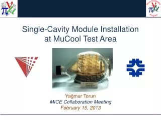
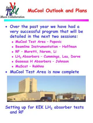
MTA • The MTA is the focus of our Activities • RF testing (805 and 201 MHz) • Installation/commissioning of Cryo-Infrastructure • High pressure H2 gas-filled RF • LH2 Absorber tests • High Intensity Beam • Will start with low intensity
MTA Cryo-Infrastruture Compressor Installation and piping are complete Heat exchanger Towards Experimental Hall Needed for Magnet Operations and LH2 Absorber Tests • Compressor Room • Two 400 HP 2-stage oil injected screw compressors • Refrigerator Room • Tevatron satellite refrigerator to be operated on 5 K mode and 14 K mode (3” DE, 3” WE) • Helium and nitrogen Dewar
MTA Cryo Infrastructure • Our goal was to have Cryo Plant Operational by NOW • Needed signficant support from AD and PPD Cryo Groups • AD – Wet engine installation/Controls/Commissioning • PPD – Transfer line system But there was a problem • Due to resource allocation to ILC cryo work, completing the MTA Cryo by end of March did not happen • Negotiations with the Lab are in progess • Start installation effort again in earnest after shutdown cryo work is completed • New goal is to be operational late Fall • Running off 500L LHe dewars will cost the collaboration approximately $3-4k/week of magnet operation • Expensive! – Working to optimize system for most efficient use of LHe
MTA High Intensity Beam • 400 MeV beamline for the MTA has been designed • Under Craig Moore/Carol Johnstone • External Beams Department • Developed Engineering Design • Cost • Schedule • Safety Analysis • Linac Area and Beamline • Shielding Assessment for MTA • The current beam line design allows for Linac diagnostic • High-Quality emittance measurement • Our goal is to bring Low Intensity to the MTA as soon as possible MTA
Proceeding with the MTA Beam Line • Cost Estimate: $388k (including 30% contingency) • Low-Intensity initial phase • Resources: $100k from Muon Collaboration • Requests • PPD • Pulsed Extraction Magnets: $75k in FY06 M&S (not likely at present) • Magnet stand fab • AD – SWF for installation • Internal AD review November 30th. The response from the committee was positive, but they asked a number of questions. A response to these questions has been prepared has submitted. • Review Committee’s final report: • It was agreed that the basic design philosophy is sound, and that the diagnostic section will be of great use not only to the MTA, but to the general Linac operation as well. Assuming that the items in the above list are addressed, and that doing so identifies no new issues, then the committee can fully support the MTA beam line design. • Modifications in Linac area have just been completed • Isolates future MTA beam line work from Linac operations
MTA – Near Term Test Program • 805 MHz Pill Box preparation complete 11/30/05 • Low power testing and conditioning begins • Currently have reached approximately 1MV/m • 805 MHz high-power testing begins 1/1/06 • TiN coated curved Be windows tests • Various B field configurations • 201 MHz cavity testing begun 3/06 • Major Milestone has been reached • LH2 Absorber test Summer 06 • Second phase of testing with KEK convective absorber • This is dependent on new safety review
RF Cavity R and D ANL/FNAL/IIT/LBNL/UMiss
Fundamental Focus Of RF R&D • Study the limits on Accelerating Gradient in NCRF cavities in magnetic field • However • We believe that the behavior of RF systems in general can be accurately described (predicted) by • Tensile strength of the material(s) used in the cavity fabrication (T) • Local surface field enhancements (beq) Esurf = £ Ö(2T/eo)/beq • This applies to all accelerating structures • In SC structures local heating becomes problem first • Follows universal curve
Phase I of RF Cavity Closed Cell Magnetic Field Studies (805 MHz) • Data seem to follow universal curve • Max stable gradient degrades quickly with B field • Sparking limits max gradient • Copper surfaces the problem Gradient in MV/m Peak Magnetic Field in T at the Window
Phase II of 805 MHz studies • Study breakdown and dark current characteristics as function of gradient and applied B field in Pillbox cavity • Curved Be window Test • TiN coated • Cavity has been conditioned to 32MV/m without B field • Measurements at 2.5T • So Far – stable gradient limited to about 14MV/m • Button test • Evaluate various materials and coatings • Quick Change over
RF R&D – 201 MHz Cavity Design • The 201 MHz Cavity is now operating • Recently reached 16MV/m at B=0! (design gradient)
Local Electrode Atom Probe (LEAP) Tomography • Atom probe experiments in collaboration with Northwestern U. Prof. David Seidman Jason Sebastian (Northwestern), P. Bauer, C. Boffo (FNAL), J. Norem (ANL) • High Gradient material studies relevant to both NCRF and SCRF – ILC, Neutrino Factory, Muon Collider, CLIC. • Surface microstructure • Surface contamination (oxides etc.) • Breakdown and Dark Currents • Data from these tests expand our knowledge of breakdown phenomena, will allow us to develop a detailed model of the physics of breakdown in cavities, and can provide a guide for materials/fabrication procedures for RF cavities Modeling Fracture Atom Probe Data from Nb sample @ ~10 GV/m
High Pressure H2 Filled Cavity WorkMuon’s Inc • High Pressure Test Cell • Study breakdown properties of materials in H2 • In B field next
Absorber R and D IIT/KEK/NIU/Osaka/UMiss
Absorber Design Issues • 2D Transverse Cooling and • Figure of merit: M=LRdEm/ds M2 (4D cooling) for different absorbers H2 is clearly Best - Neglecting Engineering Issues Windows, Safety
Absorber Design Issues • Design Criteria • High Power Handling • Study II – few 100 W to 1 KW with “upgraded” (4MW) proton driver • 10 KW in ring cooler • Must remove heat • Safety issues regarding use of LH2 (or gaseous H2) • Window design paramount • H2 containment • Proximity to RF adds constraints (ignition source) • Two Design Approaches • Convective Cooling • Shown to the right • Forced flow • High power handling H2 implies engineering complexity
Convective Absorber Activities • First Round of studies of the KEK absorber performed in the MTA • GHe used to input power
Convective Absorber Activities III • Next Round of tests will use a modified absorber • Test • Electrical Heater • New Temperature sensors • LH liquid level sensor Absorber Body being modified in Lab 6 at Fermilab
Forced-Flow Absorber • Heat removed with external heat exchanger • LH2 pumped from absorber to heat exchanger • Nozzles in flow path establish turbulent flow • Simulation via 2D and 3D FEA • Preliminary engineering design for implementation in the MTA • Have taken possession of cooling loop & heat exchanger from SAMPLE experiment @ Bates/MIT • Prototype Absorber manifold has been fabricated
MuCool Plans for the Coming Year • After a long pause due to the loss of our 805 MHz RF test facility in Lab G at Fermilab, we are now up and running again • 805 MHz RF studies (with and without B field) • Be Window tests • Materials tests • Surface treatment • Use information from LEAP studies • 201 MHz RF test program off to a Rousing start! • B field tests • Curved Be Windows • Second round of tests with KEK convective absorber • IIT ME thesis student to work on flow-absorber simulation and test • Complete MTA cryo infrastructure installation and commission system • Continue installation of 400 MeV beam line from Linac to the extent that resources allow • Have the capability for low-intensity experiments RF Highest Priority!
The MuCool Test Area Potential • The MuCooL Test Area is becoming a tremendous resource • It has the potential to provide a Unique (World-wide) R&D facility • Multi-frequency RF test capability (NC and SC) • Hydrogen Safety • Absorbers • Gas-filled RF cavities • Cryo-infrastructure (LN, high capacity LHe) • High-Intensity beam