Download
1 / 40
400 likes | 524 Views
MuCool Overview and Plans. Muon Cooling R&D MUTAC 04 A. Bross. This Review. MuCool presentations for this afternoon Overview Bross NCRF Li RF Studies Torun LH 2 Absorber Windows Cummings LH 2 Absorber Tests Ishimoto Cooling Channel Instrumentation Errede

E N D
MuCool Overview and Plans Muon Cooling R&D MUTAC 04 A. Bross
This Review • MuCool presentations for this afternoon • Overview Bross • NCRF Li • RF Studies Torun • LH2 Absorber Windows Cummings • LH2 Absorber Tests Ishimoto • Cooling Channel Instrumentation Errede • Gaseous Cooling Johnson
The MuCool Collaboration • Mission • Design, prototype and test all cooling channel components • Perform high beam-power engineering test of cooling section • Support MICE (cooling demonstration experiment) • Consists of 18 institutions from the US, Europe, and Japan RF Development ANL Fermilab IIT JLAB LBNL Univ. of Mississippi Absorber R&D Fermilab IIT KEK NIU Oxford UIUC Univ. of Mississippi Univ. Osaka Cooling Demonstration (MICE) ANL BNL Fermilab Fairfield IIT Iowa JLab LBNL NIU UCLA UC Riverside UIUC Univ. of Chicago Univ. of Mississippi Beam Diagnostics ANL Fermilab IIT Princeton Univ. of Chicago Solenoids LBNL
MuCooL Management Structure • Spokesperson and Technical Area Leaders: • Spokesperson: Alan Bross • Technical Area Leaders: • RF: Al Moretti, FNAL Derun Li, LBNL • RF Diagnostics: Yagmur Torun, IIT • Absorbers: Mary Anne Cummings, NIU • MuCooL Test Area: Milorad Popovic, FNAL
SFOFO Cooling Lattice • R&D Focus of MuCool • Component testing Fermilab • High Power • Both RF and Beam • System test - MICE @ RAL 2002 2001 2003 2004
Research and Development Challenges • Can NCRF cavities be built that provide the required accelerating gradients? • AND operate in multi-tesla fields! • Can the heat from dE/dx losses be adequately removed from the absorbers? • On the order of 100’s W for a neutrino factory • Can the channel be engineered with an acceptably low thickness of non-absorber material in the aperture? • Absorber, RF, & safety windows • Can the channel be designed & engineered to be cost effective?
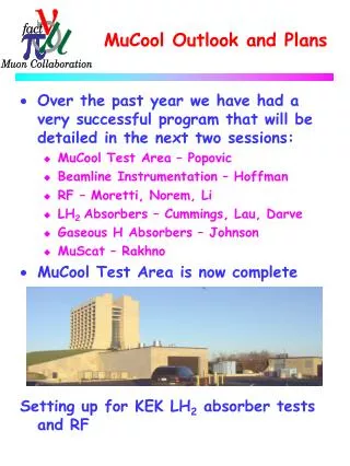
MuCool Test Area The MuCooL Collaboration Enters a new Era “Escape from the Wilderness”
MuCool Test Area • Facility to test all components of cooling channel (not a test of ionization cooling) • At high beam power • Designed to accommodate full Linac Beam • 1.6 X 10¹³p/pulse @15 Hz • 2.4 X 10¹⁴ p/s • » 600 W into 35 cm LH2 absorber @ 400 MeV • RF power from Linac (201 and 805 MHz test stands) • Waveguides pipe power to MTA Is Now Complete!
MTA • The MTA is becoming our focus of Activity • LH2 Absorber tests • RF testing (805 and 201 MHz) • Finish Cryo-Infrastructure • High pressure H2 gas absorbers • High Intensity Beam
MTA Tour Compressor Room Access Pit
MTA Tour H2 Buffer Tank H2 Manifold Room
MTA Tour Access Pit
MTA Tour MTA Experimental Hall
MTA Tour KEK LH2 Absorber
MTA Tour MTA Experimental Hall From Linac (Lots of Activity)
MTA Tour View from Wilson Hall RF Trench visible
MTA – RF Configuration KEK Absorber Currently plan to operate either RF or LH2/H2 tests, but not both simultaneously. We are discussing with the Laboratory how we can work in both modes simultaneously.
MTA Cryo-Infrastruture Heat exchanger Transfer line connections to experimental hall which includes 5K, 20K, 80K circuits Towards Experimental Hall • Compressor Room • Two 400 HP 2-stage oil injected screw compressors • Refrigerator Room • Tevatron satellite refrigerator to be operated on 5 K mode and 14 K mode (3” DE, 3” WE) • Helium and nitrogen Dewar
MTA High Intensity Beam • FNAL Study group has been formed to design 400 MeV beamline for the MTA • Under Craig Moore • External Beams Department • Develop Engineering Design • Cost • Schedule • Safety Analysis • Linac Area and Beamline • Shielding Assessment for MTA • Essentially Complete • Preliminary thoughts • “Spin” beam in order to provide large (30 cm) aperture • Instead of large Quads • Simpler and therefore Cheaper • Timeline still driven by resource availability MTA
MTA Shielding Assessment • Conclusions from Present Study • A credible beam accident at MTA is less severe than normal operation. • At normal operation the following classification is suggested (Fermi RCM): • • Berm above target hall – Controlled Area of minimal occupancy (0.25 – 5 mrem/hr); • • Access pit – Radiation Area with rigid barriers/locked gates (5 – 100 mrem/hr); • • Cryo room - Radiation Area with rigid barriers/locked gates (5 – 100 mrem/hr); • • Compressor room - Controlled Area of minimal occupancy (0.25 – 5 mrem/hr); • • Parking lot – Normal (not controlled) area (dose rate below 0.05 mrem/hr).
RF Cavity R and D ANL/FNAL/IIT/LBNL/UMiss
RF Cavity R&D – Prototype Tests • Work to date has focused on using 805 MHz cavities for test • Allows for smaller less expensive testing than at 201 MHz • Lab G work at Fermilab • Unfortunately due to a Klystron failure in the Linac, the Lab G Klystron had to be moved back to the Linac • As of December 25, 2003 the Lab G facility ceased operation • We are now moving as rapidly as possible (with a great deal of support from the Fermilab Beams Division) to bring up 805 and 201 MHz RF test capability to the MTA • Moving Vacuum, power, etc systems to MTA • Move Magnet to MTA Lab G RF Test Cave showing 5T SC Magnet 44 cm bore R.I.P.
RF Cavity R&D – Quick Review • Open cell cavity reached peak surface field of 54 MV/m (25 on axis) • Large dark currents • Damage to windows • Punctured Ti window in worst case • Closed Cell (single) cavity • B=0, Cu window – Low Bkg. • Reached 34MV/m • With B field • TiN coated Be window (0.01”) • Initially conditioned to 16MV/m • Dark currents then rose • However, no damage in evidence to Be • Copper contamination • From iris/flange surface • At 8MV/m dark currents very low • Acceptable for MICE Closed Cell Cu window
RF Cavity Closed Cell Magnetic Field Studies • Data seem to follow universal curve • Sparking limits max gradient • Copper surfaces the problem Gradient in MV/m Peak Magnetic Field in T at the Window
RF R&D – 201 MHz Cavity Design • Design Complete and Fabrication well under way • Expect Epksurf = 19 MV/m (17 MV/m on axis) • Now has curved windows • Goal is to have a 201 MHz cavity under test at Fermilab in the Fall Cavities in Coupling Coil
Tube DIA(cm) Grid 0.50 1.00 1.25 1.50 4x4-Connected 3.60 4x4 -Waffle 2.30 1.80 6x6 -Waffle 1.64 1.40 1.39 6x6 Middle-Concentrated/Waffle 1.40 RF R&D – 201 MHz Cavity DesignTube-Grid Aperture Study • Finite Element analysis of tube grid design • First applied to electromagnetic model of 805 MHz cavity • For Lab G test Grid Model Electric Field Magnetic Field Maximum Surface Field Enhancement Thesis work of Mohammad M. Alsharo’a IIT
Absorber R and D IIT/KEK/NIU/Osaka/Oxford/UIUC/UMiss
Absorber Design Issues • 2D Transverse Cooling and • Figure of merit: M=LRdEm/ds M2 (4D cooling) for different absorbers H2 is clearly Best - Neglecting Engineering Issues Windows, Safety
Absorber Design Issues • Design Criteria • High Power Handling • Study II – few 100 W to 1 KW with “upgraded” (4MW) proton driver • 10 KW in ring cooler • Must remove heat • Safety issues regarding use of LH2 (or gaseous H2) • Window design paramount • H2 containment • Proximity to RF adds constraints (ignition source) • Window material must be low Z and relatively thin in order to maintain cooling performance H2 implies engineering complexity
Absorber R&D • Two LH2 absorber designs are being studied • Handle the power load differently Forced-Convection-cooled. Has internal heat exchanger (LHe) and heater – KEK System Forced-Flow with external cooling loop
Convection Absorber • Convection is driven by beam power and internal heaters • LHe heat exchanger removes heat from absorber walls • Two-dimensional Computational Fluid Dynamics calcs • Flow essentially transverse • Max flow near beam • Heaters required to setup convective loops
Forced-Flow Absorber • Heat removed with external heat exchanger • LH2 pumped from absorber to heat exchanger • Nozzles in flow path establish turbulent flow • Simulation via 2D and 3D FEA
Absorber Windows Containment Windows • Thin windows are required in all absorber designs • Critical design issue • Performance • Safety • First examples made with AL T6061 • Maybe even thinner with • Al-Li alloy - 2195 Absorber Vacuum Design Iteration HemiSpherical – Inflected (Now also used for RF)
Gaseous Absorber – Muons Inc • Work on STTR Phase II • 805 MHz test cell • Tested at Lab G • Cell conditioned at 450 psig @ 80K • Max stable gradient • » 80 MV/m • Data agree well with Paschen Law up to » 200 psig
Beam line Instrumentation • CVD Diamond • For beam diagnostics can be very thin • Lots of charge – 36 e-h/mm-mip • Rad Hard • Low-quality (small mfp) might be useable • First prototypes have been tested • Very Fast (limited by electronics) • Large signal • Some of the diamond is approx. linear over full intensity range (3 X 10¹¹ e-/cm2) • Needs more study • MTA Instrumentation • Intrinsically safe solution • Temperatures, Magnet currents, BPMs. • Local readout (PC) + ACNET
Simulation Work • Cooling Components as mentioned • Absorbers – 2D and 3D Finite Element Analysis (FEA) 2D Computational Fluid Dynamics (CFD) • RF – Electromagnetic modeling of Be windows and grids FEA modeling of window deflection/stress • Quad-focused cooling channel • Study II cooling channel • GEANT4 simulation including latest window design • MICE • GEANT4 framework developed
MuCool and MICE • Muon Ionization Cooling Experiment (MICE) • Demonstration of “Study II” cooling channel concept • MuCool Collaboration interface to MICE • Design Optimization/develop of Study II cooling channel • Simulations • Detailed engineering • Full component design • Systems integration • Safety • RF cavity development, fabrication, and test • Absorber development, fabrication, and test • Development of beam line instrumentation • MuCool will prototype and test cooling hardware including MICE pieces for which the collaboration is responsible • High-intensity Beam Tests are responsibility of MuCool and are, of course, fully complementary to MICE
MuCool Plans • Continue development of thin windows for absorbers • Already within the material budget of Study II even with the extra windows • Begin work in the MuCool Test Area (MTA) • KEK LH2 absorber test first. Phase I complete by mid-May, second set of tests in August • Provide 201 & 805 MHz capability for MTA • Move Lab G magnet to MTA • Continue 805 MHz RF studies in Lab MTA (starting in June) • Window and grid tests • Surface treatment/materials tests • Effect on dark current and breakdown • Provide as much of the cryo infrastructure as funding allows • Very likely ALL of it • Fabricate first 201 MHz cavity and bring to MTA for test • On Schedule for delivery in Fall • In FY05 • Start 201 MHz RF test program in MTA • 805 MHz testing likely to continue interleaved with 201 testing • Complete MTA cryo (if needed) • Fabricate coupling-coil prototype • If funding is available • Begin installation of 400 MeV beam line from Linac • In FY06 • Bring high intensity beam to MTA • Test complete set of cooling components in high intensity beam
Conclusion • Excellent progress has been made in the last year • MTA is complete • On budget and on schedule • HVAC is late • Absorber testing underway • RF test program to begin in June (805 and then 201 in Fall) • NCRF R&D has demonstrated High Gradient low dark current operation • R&D continues in order to continue to push HG Low DC operation in B field • Use of Be RF windows looks promising • Design of LH2 absorbers and windows has matured • “Thin” window required spec appears to have been met • Detailed engineering of components has matured • MuCool is a thriving International Collaboration • Absorbers – Japan • Absorber/Window design – UK • Addressing many of the needs of MICE