Download

1 / 30
440 likes | 1.03k Views
Pile Capacity Based on Dynamic Methods & Wave Equation. Bigman Hutapea-Prodi Teknik Sipil,FTSL-ITB Sebagian besar materi diambil dari materi kursus singkat oleh Peter J. Bosscher- University of Wisconsin-Madison. Presentation Overview. Dynamic Formulas Dynamic Analysis Using Wave Equation

E N D
Pile Capacity Based on Dynamic Methods & Wave Equation Bigman Hutapea-Prodi Teknik Sipil,FTSL-ITB Sebagian besar materi diambil dari materi kursus singkat oleh Peter J. Bosscher- University of Wisconsin-Madison
Presentation Overview • Dynamic Formulas • Dynamic Analysis Using Wave Equation • Dynamic Pile Testing and Analysis
Dynamic Formulas • To predict static load capacity based on the foundation’s response to dynamic loads • This technique probably harkens back to when people first began driving piles • Based upon pile set (per blow) information obtained during driving • Engineers tried to base on energy concepts equating hammer kinetic energy to resistance of pile penetration (difficult and easy to drive) • ENR proposed by Wellington in 1893
Dynamic Formulas • Basic Equation:where: W = ram weight h = ram stroke R = soil resistance sb = pile set per blow (diperoleh di lapangan) • Due to simplicity, widely used • Variations exist which consider pile weight, energy losses, etc.
Do They Work? • From pioneer foundation engineer, Lazarus White (1936): “I read some of the papers last night where some of these pile driving formulas were derived, and the result was that my sleep was very much disturbed”. • ASCE Committee on Pile Foundations, 1941
Karl Terzaghi’s Response “In spite of their obvious deficiencies and their unreliability, the pile formulas still enjoy a great popularity among practicing engineers, because the use of these formulas reduces the design of pile foundations to a very simple procedure. The price one pays for this artificial simplification is very high. In some cases the factor of safety of foundations designed on the basis of the results obtained by means of pile formulas is excessive and in other cases significant settlements have been experienced. On account of their inherent defects all the existing pile formulas are utterly misleading as to the influence of vital conditions, such as the ratio between the weight of the pile and the hammer, on the result of the pile driving operations. In order to obtain reliable information concerning the effect of the impact of the hammer on the penetration of the piles it is necessary to take into consideration the vibrations which are produced by the impact.” (Terzaghi, 1943)
Why are dynamic formulae inaccurate? • Improper modeling of: • driving system • kinetic energy is not full picture • ram, anvil, helmet, cushion(s) all have effect • soil • does not resist with constant force • rapid soil resistance different than static • pile • not rigid but rather flexible • pile length has effect
Dynamic Formulae Summary • Except where well supported empirical correlations under a given set of physical and geological conditions are available, dynamic formulas should not be used. This is especially true of the ENR formula.
Alternative Methods • Wave Equation Analysis Programs (WEAP) • Dynamic Testing and Analysis Tools (Pile Driving Analyzers [PDA]) • Further improvements with CAPWAP
Dynamic Analysis Using Wave Equation • Involves the mathematical modeling of all elements in pile driving: hammer, cushions, helmet, pile, and soil. • Developed by E.A.L. Smith (1960) • Software: • TTI (1976) in public domain • WEAP (1976, 1986) in public domain • GRLWEAP (continued updates) commercial
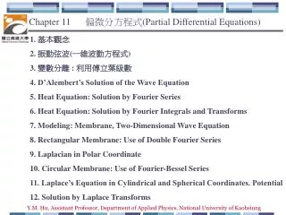
6 5 4 3 2 1 0 0 5 10 15 20 25 The Wave Equation • Provides two important items: • a guide in the selection of properly sized driving equipment and piling to ensure the pile can be driven to the final grade without exceeding allowable driving stresses; and • a penetration rate (minimum number of blows per inch of penetration) for impact hammers to determine when the pile has been driven sufficiently to develop the required capacity. From WEAP Capacity/Pile Area (ksi) Number of blows/inch (N)
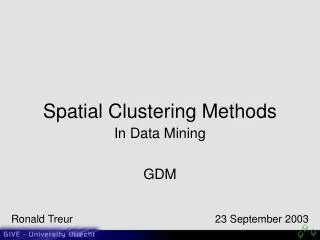
Hasil Analisis Sebelum PemancanganHubungan Ru Terhadap Final Set Untuk Energi Yang Bervariasi
Benefits of WEAP during Design • Can design pile section for driveability to the required depth and/or capacity • Can select pile material properties based on probable driving stresses • Can justify new depths, design loads, and/or different number of piles
Benefits of WEAP during Construction • Construction engineers can use for: • hammer approval and cushion design • to select an economical combination of driving equipment to minimize installation cost
Proper Use of WEAP • Note: the wave equation does not determine the capacity of the pile based on soil boring data. • It calculates driving resistance for an assumed ult. capacity or calculates capacity based on field observed driving resistances. • Therefore, precede WEAP w/ static analysis • Be prepared for pile setup (EOD vs BOR)
Dynamic Pile Testing and Analysis (PDAs) • Based on measurements of strain and acceleration taken near the pile head as a pile is driven or restruck with a pile driving hammer • Can be used to evaluate the performance of the pile driving system, calculate pile installation stresses, determine pile integrity, and estimate static pile capacity
Pile Driving Analyzer • Strain transducer: strain data, combined with the modulus of elasticity and cross-sectional area of the pile gives the axial force in the pile • Accelerometers: the acceleration data, double integrated with time produces the pile displacement during the hammer blow. • Pile Driving Analyzer (PDA)
Pile Driving Analyzers • Other measurements are sometimes made such as the ram velocity (with radar or the time between two impacts of the ram). • This information is plugged into a closed form solution (based on an assumption of ideal plastic soil behavior and ideal elastic and uniform piling) called the Case Method.
The Case Method • Given the measured pile top force F(t) and the pile top velocity v(t), the total soil resistance is: • whereZ = EA/c = pile impedancet2 = time = t1 + 2L/cL = pile length below the gaugesc = (E/)0.5 = speed of the stress waveE = elastic modulus of the pile = pile mass densityA = pile cross sectional area
The Case Method • The total soil resistance consists of a dynamic and a static component. • The static component is the desired pile bearing capacity. • The dynamic component may be computed from a soil damping factor, J, and a pile toe velocity, vt(t), which is calculated for the pile toe. The equation used is:
Pile Driving Analyzer Limits • Calculates pile stress at gage location but maximum stress may occur elsewhere (eg: end bearing pile) • Judgement required to distinguish between low displacement piles or piles with large shaft resistance versus piles with large toe resistances. • CAPWAP provides more information
CAPWAP: Case Pile Wave Analysis Program • combines the wave equation model with Case Method measurements • uses single-blow record from EOD or BOR • method iteratively determines several unknowns by signal matching • determines stresses along the pile
Benefits/Losses of PDAs • Provides record of pile installation (QC) • Fairly quick and painless (except $$$) • Can reduce amount of static pile testing • Hard driving (>10 blows/inch) can yield lower bound capacities • Estimate of static pile capacity at time of testing (i.e.:may not include soil setup). • Piles which do not form soil plug may indicate lower capacity dynamically versus actual static capacity