Download
1 / 97
1.08k likes | 1.12k Views
KINEMATICS OF MACHINERY. Presented by VVR MURTHY M.Tech , Assistant Professor DEPARTMENT OF MECHANICAL ENGINEERING VISAKHA INSTITUTE OF ENGINEERING & TECHNOLOGY. Mechanics. Dy n amics. S t atics. Kin e tics. Kin e matics.

E N D
KINEMATICS OF MACHINERY Presented by VVR MURTHY M.Tech, Assistant Professor DEPARTMENT OF MECHANICALENGINEERING VISAKHA INSTITUTE OF ENGINEERING & TECHNOLOGY
Mechanics Dynamics Statics Kinetics Kinematics By -T.S.SENTHILKUMAR/AP
The branch of scientific analysis that deals with motions, time and forces is called mechanics. • It is divided in to two parts statics and dynamics. By -T.S.SENTHILKUMAR/AP
STATICS • It deals with the analysis of stationary systems. But time is notconsidered. • DYNAMICS • It deals with the systems that changewith time. By -T.S.SENTHILKUMAR/AP
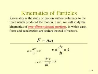
KINEMATICS • It is the study of motion, quite apart from the forces which produce thatmotion. • It is the study of position, displacement, rotation, speed, velocity andacceleration. • KINETICS • It is the study of motion and itscauses By -T.S.SENTHILKUMAR/AP
The subject matter which deals with this geometric constant of relative motion, without any reference to the cause of the motion that is the force is calledkinematics. For the study of kinematics, a machine may be referred to as a mechanism, which is a combination of inter connected rigid bodies capable of relativemotion. By -T.S.SENTHILKUMAR/AP
Machinery is defined as a mechanical device or the parts that keep somethingworking. Machines or machine parts considered as agroup. The working parts of a particularmachine. An assemblage ofmachines. The parts of a machinecollectively. An assemblage of machines or mechanical apparatuses By -T.S.SENTHILKUMAR/AP
It is defined as the combination of rigid or resistance bodies assembled in such a way that the motion of one causes constrained and predictable motion to others is known as mechanism. • If one of the links of a kinematic chain is fixed, then the chain is known asmechanism. By -T.S.SENTHILKUMAR/AP
An assembly of moving parts performing a complete functionalmotion. A mechanism is a device designed to transform input forces and movement into a desired set of output forces andmovement. Mechanisms generally consist of moving components such as gears and gear trains, belt and chain drives, cam and follower mechanisms, and linkages as well as friction devices such as brakes and clutches, and structural components such as the frame, fasteners, bearings, springs, lubricants and seals, as well as a variety of specialized machine elements such as splines, pins andkeys. By -T.S.SENTHILKUMAR/AP
It is defined as a device which receives energy and transforms it into some usefulwork. • If the mechanism is used to transmit power (or) to do work, then it is known asmachine. • The main function of the machine is to obtain mechanicaladvantage. By -T.S.SENTHILKUMAR/AP
We can define machine as a device for transferring and transforming motion and force or power from the input that is, the source to the output that is theload. The motion needs to be transformed as it is being transferred from the source to theload. By -T.S.SENTHILKUMAR/AP
It is a resistant body or assembly of resistant body of a machine connecting other parts of the machine with relative motion between them. • There are three types of links available in order to transmit motion. They are asfollows: • » Rigidlink • » Flexiblelink • » Fluidlink By -T.S.SENTHILKUMAR/AP
Rigidlink A rigid link is one which does not undergo any deformation while transmitting motion. Practically rigid link does not exists. Ex : crank shaft, pistonetc., Flexiblelink A flexible link is one which undergoes partial deformation without affecting the transfer motion. Ex : ropes, belts, chains, springsetc., Fluid link A fluid link is a link which has fluid inside the container and motion is transmitted through the fluid by pressure or compression. Ex: fluids used in hydraulic press, hydraulic jack, hydraulic craneetc., By -T.S.SENTHILKUMAR/AP
Binary link, Ternary link, Quaternarylink By -T.S.SENTHILKUMAR/AP
A joint of two links that permits relative motion is calledpair. • Types of kinematicpair • Nature of relative motion between thelinks. • Nature of contact between thelinks. • Nature of mechanicalarrangement. By -T.S.SENTHILKUMAR/AP
» Slidingpair » Turningpair » Cylindricalpair » Rollingpair » Sphericalpair » Helicalpair Nature ofcontact » Lowerpair » Higherpair Nature of mechanicalconstraint » Closedpair Nature of relativemotion » UnclosedpBayi-rT.S.SENTHILKUMAR/AP 11/10/2016 17
Slidingpair By -T.S.SENTHILKUMAR/AP
Turningpair By -T.S.SENTHILKUMAR/AP
Cylindricalpair By -T.S.SENTHILKUMAR/AP
Rollingpair By -T.S.SENTHILKUMAR/AP
Sphericalpair By -T.S.SENTHILKUMAR/AP
Helical pair or screwpair By -T.S.SENTHILKUMAR/AP
Lowerpair By -T.S.SENTHILKUMAR/AP
Higherpair By -T.S.SENTHILKUMAR/AP
Closedpair • When two elements of a pair are held together mechanically, they constitute a closedpair. • Ex : Allpair • Un closedpair • When two elements of a pair are not held together mechanically, they constitute a unclosed pair. • Ex : cam andfollower By -T.S.SENTHILKUMAR/AP
If the last link is joined to first link to transmit definite motion, then it is known as kinematic chain. • To determine the given assemblage of links form the kinematic chain ornot: • The two equationsare: l = 2p –4 • j = (3/2) * l –2 • Where, l = number oflinks p = number of pairs j = number ofjoints By -T.S.SENTHILKUMAR/AP
Completely ConstrainedMotion Constrained Motions Uncompletely ConstrainedMotion Successfully ConstrainedMotion By -T.S.SENTHILKUMAR/AP
JOINTS Quaternary joint Ternary joint Binaryjoint By -T.S.SENTHILKUMAR/AP
The analysis of mechanism is the number of degrees of freedom, also called the mobility of thedevice. The mobility of a mechanism is defined as the number of input parameters which must be controlled independently in order to bring the device in to a particularposition. It is the number of independent coordinates required to describe the position of a body in space. By -T.S.SENTHILKUMAR/AP
Movability includes the six degrees of freedom of the device as a whole, as through the ground link were not fixed and thus applies to a kinematicchain. Mobility neglects these and considers only the internal motions, thus applying to a mechanism. By -T.S.SENTHILKUMAR/AP
A link is to have ‘n’ degree of freedom if it has n independent variables associated with itsposition in theplane. By -T.S.SENTHILKUMAR/AP
Then the number of degree of freedom of a mechanism (n) is givenby, n = 3 (l-1) – 2j – h where, l= number of links j = number of binaryjoints h = number of higherpairs This equation is called kutzbach criterion for the mobility of amechanism. If there is no higher pair, then h = 0. then kutzbach criterion, n = 3 (l-1) –2j By -T.S.SENTHILKUMAR/AP
Mechanism with lowerpairs • Three barmechanism • Four barmechanism • Five barmechanism • Six bar mechanism • Mechanism with higherpairs By -T.S.SENTHILKUMAR/AP
Where,n = Number of degree offreedom l = Number oflinks P1 = Number of pair having one degree of freedom P2 = Number of pair having two degree of freedom n = 6(l-1) – 5P1 – 4P2 – 3P3 – 2P4 –1P5 By -T.S.SENTHILKUMAR/AP
Grubler’s mechanism is obtained by substituting n = 1 and h = 0 in Kutzbach criterion asbelow. we know that, n = 3 (l-1) – 2j -h l= 3 (l -1) – 2j or 3l – 2j – 4 =0 This equation is known as Grubler’s criterionfor planemechanism By -T.S.SENTHILKUMAR/AP
We know that Kutzbach criterion for spatial mechanismis n = 6(l-1) – 5P1 – 4P2 – 3P3 – 2P4 –1P5 substitute n = 1; P2, P3 , … P5 =0 1 = 6(l-1)–5P1 (or) 6l – 5P1 – 7 =0 This equation is known as Grubler’s equationfor spatialmechanism. By -T.S.SENTHILKUMAR/AP
When one of the links of kinematic chain is fixed, then the chain is known asmechanism. By -T.S.SENTHILKUMAR/AP
Simplemechanism Compoundmechanism By -T.S.SENTHILKUMAR/AP
When Connected As PerKutzbach’s Criterion Kinematic Chain Kinematic Pair When Forces And Couples AreTransmitted When OneLink IsFixed Mechanism Machine By -T.S.SENTHILKUMAR/AP
The method of obtaining different mechanisms by fixing different links in a kinematic chain, is known as inversion of themechanism. By -T.S.SENTHILKUMAR/AP
Kinematicchain Slidercrank chain Doublecrank chain Four barchain By -T.S.SENTHILKUMAR/AP
Inversion Of Four BarChain Watt’s Indicator Mechanis m Ackerman n Mechanis m Coupled Locomotiv eWheels Beam Engine Pantograph By -T.S.SENTHILKUMAR/AP
Beam Engine First inversion second Inversion Coupling rod oflocomotive Watt’sIndicator Mechanism Pantograph Ackermann Steering ThirdInversion By -T.S.SENTHILKUMAR/AP
Mechanism.Gif\inversion of four barchain\beam- engine-o.Gif Beamengine By -T.S.SENTHILKUMAR/AP
Coupling rod of alocomotive By -T.S.SENTHILKUMAR/AP
Watt’s indicatormechanism By -T.S.SENTHILKUMAR/AP
Pantograph By -T.S.SENTHILKUMAR/AP