Download
1 / 100
1.05k likes | 1.08k Views
KINEMATICS OF MECHINERY. KINEMATICS OF MECHINERY. Unit – I-Basics of Mechanism Unit – II – Kinematics Unit – III – Cams Unit – IV – Gears Unit – V - Friction. 1.Terminologies Machine Mechanism Kinematic Pair Links Kinematic Chain 2.DOF Kutzhback Equation Grubler Equation.

E N D
KINEMATICS OF MECHINERY Kinematics of Machinery - Unit - I
KINEMATICS OF MECHINERY • Unit – I-Basics of Mechanism • Unit – II – Kinematics • Unit – III – Cams • Unit – IV – Gears • Unit – V - Friction Kinematics of Machinery - Unit - I
1.Terminologies Machine Mechanism Kinematic Pair Links Kinematic Chain 2.DOF Kutzhback Equation Grubler Equation 3.Grashoff Law 4.Mechanism Four Bar Single-Slider Crank Double-Slider 5.Inversion of Mechanism 6.Mechanical Advantage 7.Transmission Angle 8.Design of Mechanism Unit – I-Basics of Mechanism Kinematics of Machinery - Unit - I
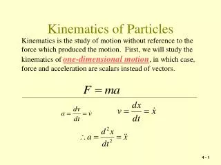
MECHANISM Mechanism – Part of a machine, which transmit motion and power from input point to output point Kinematics of Machinery - Unit - I
Example for Mechanism Kinematics of Machinery - Unit - I
Example for Mechanism Kinematics of Machinery - Unit - I
PLANAR MECHANISMS When all the links of a mechanism have plane motion, it is called as a planar mechanism. All the links in a planar mechanism move in planes parallel to the reference plane. Kinematics of Machinery - Unit - I
MACHINE A machine is a mechanism or collection of mechanisms, which transmit force from the source of power to the resistance to be overcome. Kinematics of Machinery - Unit - I
Though all machines are mechanisms, all mechanisms are not machines Kinematics of Machinery - Unit - I
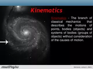
KINEMATICS Kinematics of Machinery - Unit - I
RELEVANCE OF KINEMATIC STUDY • Motion requirements • Design requirements Kinematics of Machinery - Unit - I
MOTIONSTUDY Study of position, displacement, velocity and acceleration of different elements of mechanism Given input Desired output Kinematics of Machinery - Unit - I
Motion requirement Kinematics of Machinery - Unit - I
DESIGN REQUIREMENTS Design: determination of shape and size • Requires knowledge of material • Requires knowledge of stress Requires knowledge of load acting (i) static load (ii) dynamic/inertia load Kinematics of Machinery - Unit - I
DYNAMIC/INERTIA LOAD Inertia load require acceleration Kinematics of Machinery - Unit - I
LINK OR ELEMENT Any body (normally rigid) which has motion relative to another • Binary link • Ternary link • Quaternary link Kinematics of Machinery - Unit - I
Examples of rigid links Kinematics of Machinery - Unit - I
PAIRING ELEMENTS Pairing elements: the geometrical forms by which two members of a mechanism are joined together, so that the relative motion between these two is consistent. Such a pair of links is called Kinematic Pair. Kinematics of Machinery - Unit - I
PAIRING ELEMENTS Kinematics of Machinery - Unit - I
PAIRING ELEMENTS Kinematics of Machinery - Unit - I
KINEMATIC PAIRS • A mechanism has been defined as a combination so connected that each moves with respect to each other. A clue to the behavior lies in in the nature of connections, known as kinetic pairs.The degree of freedom of a kinetic pair is given by the number independent coordinates required to completely specify the relative movement. Kinematics of Machinery - Unit - I
Based on nature of contact between elements (i) Lower pair : The joint by which two members are connected has surface contact. A pair is said to be a lower pair when the connection between two elements are through the area of contact. Its 6 types are Revolute(Or)TurningPair Prismatic(Or)SlidingPair Screw(Or)HelicalPair CylindricalPair Spherical(Or)GlobularPair Flat(or)PlanarPair TYPES OF KINEMATIC PAIRS Kinematics of Machinery - Unit - I
(ii) Higher pair: The contact between the pairing elements takes place at a point or along a line. Kinematics of Machinery - Unit - I
Based on relative motion between pairing elements (a) Siding pair [DOF = 1] (b) Turning pair (revolute pair) [DOF = 1] Kinematics of Machinery - Unit - I
Based on relative motion between pairing elements (c) Cylindrical pair[DOF = 2] (d) Rolling pair [DOF = 1] Kinematics of Machinery - Unit - I
Based on relative motion between pairing elements (e) Spherical pair [DOF = 3] (f) Helical pair or screw pair [DOF = 1] Kinematics of Machinery - Unit - I
Based on the nature of mechanical constraint (a) Closed pair (b) Unclosed or force closed pair Kinematics of Machinery - Unit - I
CONSTRAINED MOTION one element has got only one definite motion relative to the other Kinematics of Machinery - Unit - I
(a) Completely constrained motion Kinematics of Machinery - Unit - I
(b) Successfully constrained motion Kinematics of Machinery - Unit - I
(c) Incompletely constrained motion Kinematics of Machinery - Unit - I
KINEMATIC CHAIN Group of links either joined together or arranged in a manner that permits them to move relative to one another. Kinematics of Machinery - Unit - I
Kinematic Chain Relation between Links, Pairs and Joints L=2P-4 J=(3/2) L – 2 L => No of Links P => No of Pairs J => No of Joints L.H.S > R.H.S => Locked chain L.H.S = R.H.S => Constrained Kinematic Chain L.H.S < R.H.S => Unconstrained Kinematic Chain Kinematics of Machinery - Unit - I
LOCKED CHAIN (Or) STRUCTURE Links connected in such a way that no relative motion is possible. L=3, J=3, P=3 L.H.S>R.H.S Kinematics of Machinery - Unit - I
Kinematic Chain Mechanism Slider crank and four bar mechanisms L=4, J=4, P=4 L.H.S=R.H.S Kinematics of Machinery - Unit - I
Working of slider crank mechanism Kinematics of Machinery - Unit - I
Unconstrained kinematic chainL=5,P=5,J=5 L.H.S < R.H.S Kinematics of Machinery - Unit - I
DEGREES OF FREEDOM (DOF): It is the number of independent coordinates required to describe the position of a body. Kinematics of Machinery - Unit - I
Degrees of freedom/mobility of a mechanism It is the number of inputs (number of independent coordinates) required to describe the configuration or position of all the links of the mechanism, with respect to the fixed link at any given instant. Kinematics of Machinery - Unit - I
GRUBLER’S CRITERION Number of degrees of freedom of a mechanism is given by F = 3(n-1)-2l-h. Where, • F = Degrees of freedom • n = Number of links in the mechanism. • l = Number of lower pairs, which is obtained by counting the number of joints. If more than two links are joined together at any point, then, one additional lower pair is to be considered for every additional link. • h = Number of higher pairs Kinematics of Machinery - Unit - I
F = 3(n-1)-2l-h Here, n = 4, l = 4 & h = 0. F = 3(4-1)-2(4) = 1 I.e., one input to any one link will result in definite motion of all the links. Examples - DOF Kinematics of Machinery - Unit - I
F = 3(n-1)-2l-h Here, n = 5, l = 5 and h = 0. F = 3(5-1)-2(5) = 2 I.e., two inputs to any two links are required to yield definite motions in all the links. Examples - DOF Kinematics of Machinery - Unit - I
F = 3(n-1)-2l-h Here, n = 6, l = 7 and h = 0. F = 3(6-1)-2(7) = 1 I.e., one input to any one link will result in definite motion of all the links. Examples - DOF Kinematics of Machinery - Unit - I