Download

1 / 11
1.05k likes | 2.48k Views
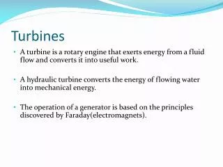
TURBOMACHINES Chapter 8 HYDRAULIC TURBINES. Classification of Hydraulic Turbines: Water turbines are classified into various kinds according to the action of water on blades, based on the direction of fluid flow through the runner and the specific speed of the machine.

E N D
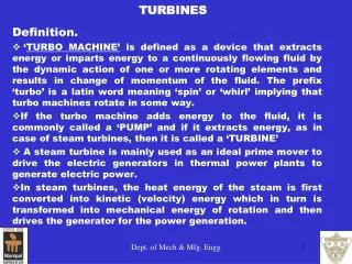
Classification of Hydraulic Turbines: • Water turbines are classified into various kinds according to • the action of water on blades, • based on the direction of fluid flow through the runner and • the specific speed of the machine. Based on the action of water blades: • These may be classified into • Impulse type • Reaction type
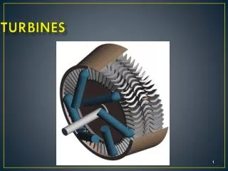
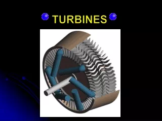
Pelton Wheel: This is only the impulse type of tangential flow hydraulic turbine. This mainly posses 1) Nozzle 2) runner & buckets 3) casing 4) brake nozzle. Fig. shows general layout of hydro-electric power plant with pelton wheel.
Work Done by the Pelton Wheel: let θ be the angle through which the jet is deflected by the bucket. β2 is the runner tip angle = 180 - θ.
Francis turbine which is of mixed flow type is as shown in fig. It is of inward flow type of turbine in which the water enters the runner radially at the outer periphery and leaves axially at its center.
Draft Tubes: • There are different types of draft tubes which are employed to serve the purpose in the installation of the turbine are as shown in the figure.
Work Done and Efficiencies of Francis Turbine: The absolute velocity at exit leaves the runner such that there is no whirl at exit i.e. the inlet velocity triangle are drawn for different conditions as shown in figure (a) & (b).
At inlet, the velocity triangle is as shown in figure. • At the outlet, the discharge is always axial with no whirl velocity component i.e. outlet velocity triangle just a right angle triangle as shown in figure.