Download

1 / 16
601 likes | 1.84k Views
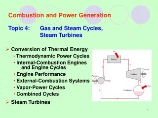
TURBOMACHINES Chapter 7 STEAM TURBINES. Steam turbines may be of two kinds, namely ( i ) impulse turbine. In Impulse turbine, the enthalpy drop (pressure drop) completely occurs in the nozzle itself and when the fluid pass over the moving blades it will not suffer pressure drop again.

E N D
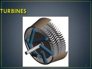
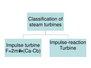
Steam turbines may be of two kinds, namely (i) impulse turbine • In Impulse turbine, the enthalpy drop (pressure drop) completely occurs in the nozzle itself and when the fluid pass over the moving blades it will not suffer pressure drop again. • Hence pressure remain constant when the fluid pass over the rotor blades. Fig. shows the schematic diagram of Impulse turbine.
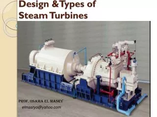
(ii) Reaction turbine. ` • In Reaction turbines, addition to the pressure drop occurs in the nozzle there will also be pressure drop occur when the fluid passes over the rotor blades. Fig. shows the Reaction turbine. • Most of the steam turbine are of axial flow type devices except Ljungstrom turbine which is a radial type.
Analysis on single stage turbine: 1. General velocity diagram of Impulse turbine: If there is no frictional loss, then the axial thrust is zero as Vf1 = Vf2 and Vr1 = Vr2
5. Condition for Maximum Utilization Factor or Blade efficiency with equiangular Blades for Impulse Turbine: Consider the velocity diagram shown in fig (a). Due to the effect of blade friction loss, the relative velocity at outlet is reduced than the relative velocity at inlet. Therefore Vr2 = Cb Vr1. Corresponding velocity triangle shown if fig (b)
Analysis on two stages: 1. Condition for maximum efficiency for velocity compounded Impulse turbine (Curtis Turbine)
Then the maximum blade efficiency is, Maximum total work done per kg of steam,
Reaction turbines: These are of axial type. But pure reaction turbine are not in general use, only impulse-reaction turbines are used. 1. The velocity triangle for general case: In reaction turbine steam continuously expands as it flows over the blades thereby increases the relative velocity of steam, i.e., Vr2 > Vr1
2. Degree of reaction (R): The degree of reaction for reaction turbine stage is defined as the ratio of enthalpy drop in the moving blades to the total enthalpy drop in fixed and moving blades (i.e., static enthalpy drop to total enthalpy drop), as shown in fig.
The variation ηb with blade speed ratio Φ for the reaction stage is shown in fig.
Effect of Reheat Factor and Stage Efficiency: Consider a turbine with n number of stages, say n = 4 as shown in fig.