Download
1 / 14
140 likes | 142 Views
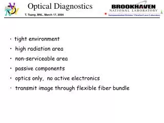
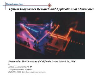
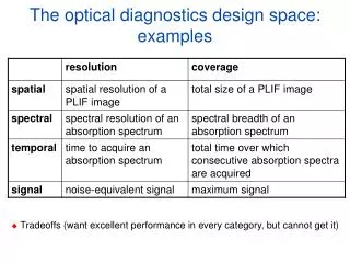
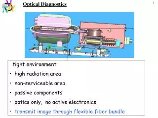
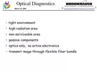
This optical diagnostics system is designed for a tight environment with high radiation. It uses passive components and optics only, with no active electronics. The system utilizes back-illuminated imaging fibers and a single fiber laser for image transmission.

E N D
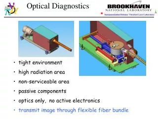
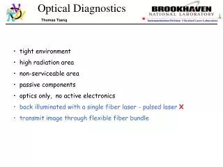
Optical Diagnostics Hg_jet_meeting, 01-18-05 Thomas Tsang • tight environment • high radiation area • non-serviceable area • passive components • optics only, no active electronics • back illuminated with a single fiber laser - pulsed laser X • transmit image through flexible fiber bundle
Optical Diagnostics Nov, 2004 @ Princeton Test target Field of view lens lens fiber bundle
Optical Diagnostics More imaging fibers New imaging fiber bundle Core size: 24 µm, Diameter: 1/4” New imaging fiber bundle Core size: 12 µm, diameter: 1/8” old fiber bundle SMD camera CCD size: 13.4 x 13.4 mm Pixels: 960x960 Single frame: 240x240 pixels Reduced pixel size: 56 x 56 um Total fiber counts ~50,000 in 3.17 mm diameter Imaging ~243 x 243 fibers on 960 x 960 CCD array ~1 imaging fiber on ~4x4 pixels on full frame ~1 imaging fiber on ~1 pixel on a single frame
Optical Diagnostics Simple back illumination ?
Optical Diagnostics Backlight illumination results cm scale test target need >500 pulse/frame ~mJ/pulse in 1-MHz reprate !! fiber backlight laser light input
Optical Diagnostics Conventional shadow illumination approach ? >12-inch away Can NOT be implemented in this tight environment !
Optical Diagnostics retroreflected illumination Spherical mirror laser illumination image collection cm scale Works OK in this tight environment test target
Optical Diagnostics Exp test setup test target • Optical Components • 50/50 beam splitter: Edmund, 0.5 cm cube • spherical mirror: Edmund, f=3-in, D=3in< Au coated • small prism mirror: Edmund, 1x1x1.4 cm, Au coated • large prism mirror: Edmund, 2.5x2.5x3.54 cm. Au coated • imaging fiber Edmund: ⅛-in diameter, 12-µm core, 0.55 NA • illumination fiber: ThorLabs, 0.22 NA, SMA-905 840 -µm core • imaging lens: Sunex, f=0.38-cm, f/# 2.6, diagonal FOV 54°, φ1.4-cm x 2.0 cm
Optical Diagnostics Field of view - imaging
Optical Diagnostics Field of view – NIR laser illumination & imaging
Optical Diagnostics optical design in secondary containment e-Drawing - Van Graves, ORNL e-Drawing - Van Graves, ORNL One set of optics per viewport Conceptual design completed
Optical Diagnostics An optical chopper in motion @ 4 kHz Stationary image 100 µs/frame Velocity @ ~40 m/s 10 µs/frame 1 µs/frame 100 µs/frame with reflective mask
Optical Diagnostics An optical chopper in motion @ 4 kHz cont’ 100 µs/frame with reflective mask Velocity @ ~40 m/s frame #12
Optical Diagnostics Other issues • Laser power increase to ~40 W/pulse (instead of 10 Watt/pulse) • Depth of focus → apparent image size variation • 3-in dia. spherical mirror (lens/mirror) with the right focal length • Anti-reflection coated (@ 800 nm) viewports • ~50-m? long flexible, square shaped imaging fiber bundles – Schott Optics • Radiation resistance of imaging fiber bundles and optics ? to be tested. • Number of viewports ? minimum of 3 • Location of the viewports ? 5-inches aparts • How many fast CCD camera ? 1 fast (1 µs) camera, 1 slower (250 µs) camera ? • Switch from one viewport to the next with one laser/camera system ? • … IG-154, 10 µm size 4 mm x 4 mm 4.5 meter long $5.7K CCD camera